13
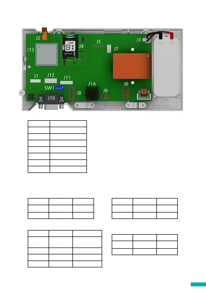
Connector Description
Description
J2 External antenna
J3 Battery
J6 Power Supply
J8 CANBus
J9/ J1A Phone line
J10 Serial connector
J11 Programmable I/O
To access dipswitches and connectors,
open the DCP case by unfastening the
front screw (using a PZ1 screwdriver) and
removing the lid.
J2 - External antenna - Connect the external antenna delivered with the kit to the
J2 connector. Only antennas approved by Avire should be used in the installation,
otherwise the device might not function properly and may be damaged.
J3 - Battery
Pin Function Signal
1 +12 Positive
2 GND Negative
J6 - Power Supply
Pin Function Signal
1 L Live
2 N Neutral
J8 - CANBus
Pin Function Signal
1 VCC Unregulated
output
2 CANH Bus CAN H
3 CANL Bus CAN L
4 GND Ground
J9/ J1A - Phone line (SLIC)
Pin Function Signal
1 L1 Tip
2 L2 Ring
Supply voltage: 100-240 VAC, 50/60 Hz
VCC is an unregulated output 10-21 VDC + battery
support 10-14 VDC