14
J10 CONNECTOR - RS-232 or 422/485 Serial Connector
The J10 connector is a standard serial communication port that allows the connection
of computers, controls or any other device that needs remote communication through
a reliable wireless data channel. The connectivity provided by the port is in real time
and acts as a point to point transmitter.
Pin Signal Pin Signal
2 TX Out 7 RTS Out
3 RX In 8 CTS In
5 Ground Ground RS-232
Pin Signal Pin Signal
2 T+ T+ RS422 7 T- T- RS422
3 R- R- RS422 8 R+ R+ RS422
5 Ground Ground RS-422
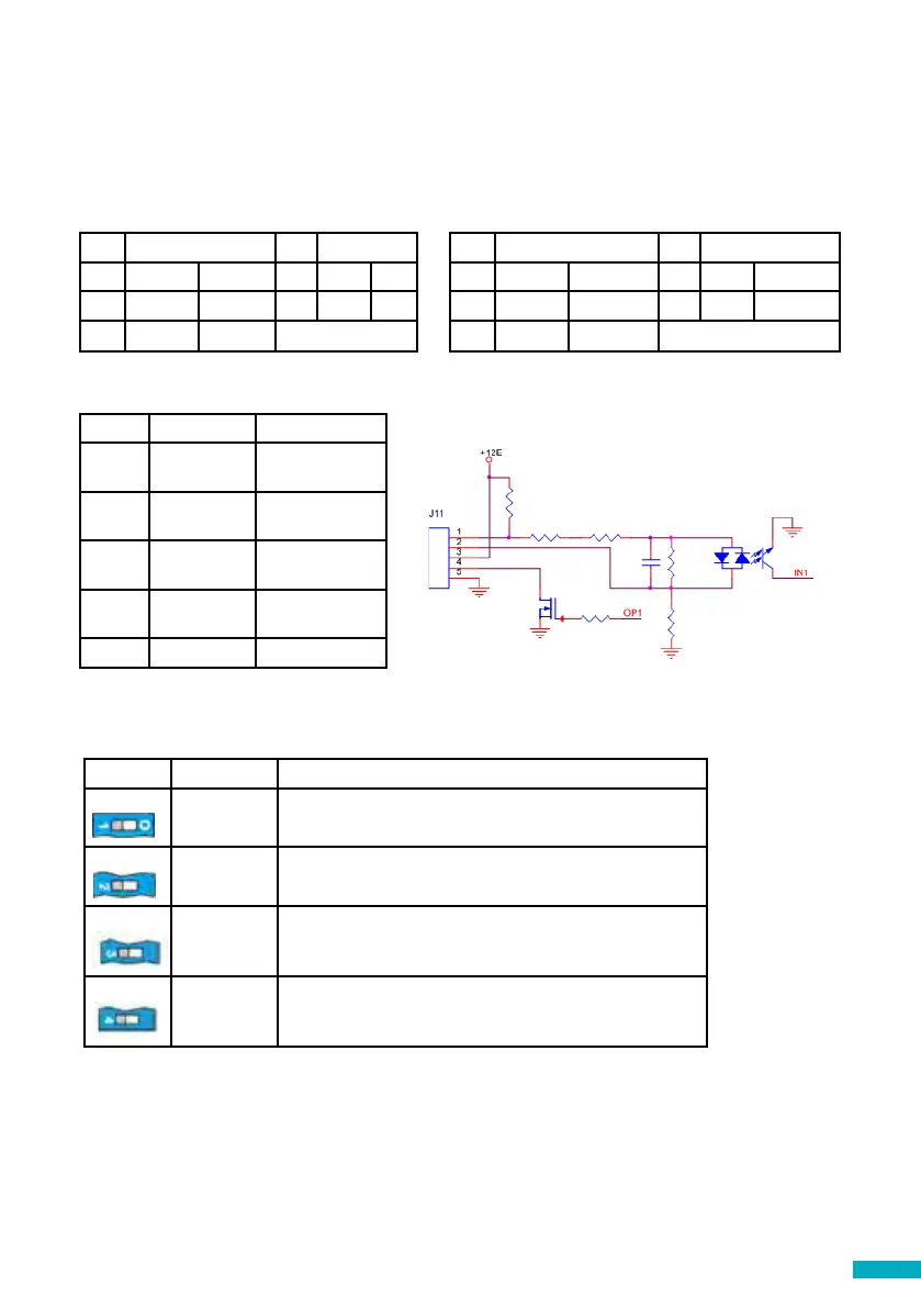
J11 - Digital Input/ Output
Pin Function Signal
1 AK1 Input Outo-
Coupler
2 AK2 Input Outo-
Coupler
3 VCC Output 10-21
VDC
4 OP1 Open collector
Mosfet N
5 GND Ground
SW1 Function Description
1
Signal tester Inbuilt signal tester
Default OFF
2
Not used Not used
3
Reserved Avire internal use only
Default OFF
4
CAN Ω Activates the CANBus End of Line (EOL) for the CAN
connector.
Default ON – DCP is typically an End of Line device.