Do you have a question about the AVIRE DCP and is the answer not in the manual?
Describes the dual SIM card version's ability to switch SIMs and use one for voice and the other for data.
Emphasizes installation by qualified personnel in restricted areas for safety.
Guides on inserting SIM cards, network registration, and checking LEDs.
Instructions for connecting the antenna and battery to the DCP unit.
Details on using the built-in network signal strength scanner.
Explains signal strength levels (Low, Medium, Optimal) using LED colors and dBm values.
Instructions for connecting the 230VAC power supply to the DCP unit via J6.
Guidance on clamping power cable, securing lid, and mounting the DCP on a wall.
Describes turning on the DCP and interpreting RUN, BAT, SIM, Coverage, and SLIC LED status.
Notes on APN settings and SIM card unlocking for non-Avire SIMs.
Method to disable SIM PIN by using a conventional mobile phone.
Steps to program SIM PIN via analogue phone connected to J1A or J9.
Procedure to remotely enter SIM PIN by sending an SMS to the DCP.
Guide to configuring APN settings using 'Super settings' based on country and network provider tables.
Details on Digit 1 (Continent), Digit 2 (SIMO Network), Digit 3 (Type of connection), and Digit 4 (SIM1 Network).
Explains commands like P060, P061, P063 for manual APN and connection type settings via SMS.
Provides examples of APN settings for Vodafone AUS, Telstra AUS, and Spark NZ.
Describes how to find the CCID number on Avire SIM cards and their outer case.
Explains retrieving the CCID for non-Avire SIMs by sending a specific SMS command.
Provides the link to the Avire Hub and information on accessing tutorial videos.
Step-by-step guide on creating a new building entry in the Avire Hub, including data fields.
Instructions for entering the number of elevator groups and elevators per group.
Steps to add the DCP 4G as a gateway in the Avire Hub, including SIM information.
Steps to save the configuration and access DCP settings like 'Access' and 'Events'.
Guide on clicking 'Read parameters' to check the connection status and view parameters.
Details on using SMS commands like P005, P020, P064, P030 etc., with their functions and default values.
Explanation of parameter P051 for dual SIM card configurations (SIMO primary, SIM1 primary, Voice/Data).
Details on the J2 external antenna connection and J3 battery pinout.
Explains the J6 power supply and J8 CANBus connector pinouts.
Describes the J9/J1A phone line (SLIC) connector and its pinout.
Details the pinout and function of the J10 serial connector for RS-232 or 422/485 communication.
Explains the functions and pinout of the J11 digital input/output connector.
Describes the functions of the SW1 dipswitch settings, including signal tester and CAN bus EOL.
Overview of the five DCP indicator LEDs (RUN, BAT, SIM, COVERAGE, SLIC) and their basic functions.
Comprehensive explanation of what ON, OFF, and FLASHING states for each LED color signify.
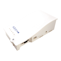
Visual identification of key system components like DCP, Triphony Unit, PIT Phone, etc.
Illustrates a typical lift car system setup involving the DCP, DAU, and other Avire units.
Diagrams showing system setups for two lift cars with various Avire components.
Illustrates a system configuration for four lift cars, including notes on limitations.
Instructions for connecting a Digital Audio Unit (DAU) and its CANBus wiring to the DCP.
Details the specific CANBus connection points on both the DCP (J8) and the DAU (J9).
Shows the connections on the DCP (J1A, J9, J6) and the corresponding connections on the Memcom+ unit.
Specifies operating environment conditions, cleaning procedures, and maintenance advice.
Covers critical safety warnings, fire risk, modification prohibitions, and hazardous area usage.
Details battery replacement intervals, authorized batteries, and proper disposal methods.
Mentions RoHS compliance and standards for wiring insulation.
The Digital Communication Platform (DCP) serves as a crucial information gateway, connecting compatible Avire devices within a lift shaft to the Avire Hub, an online monitoring platform. This device operates independently, requiring no direct connection to the lift controller panel.
The DCP facilitates seamless communication between various Avire components in the lift shaft and the Avire Hub. It acts as a central point for data transmission, enabling remote monitoring and management of lift systems. The platform supports both 3G and 4G connectivity, with options for single or dual SIM card configurations. The dual SIM card version offers enhanced reliability by allowing automatic switching between SIM cards if a connection is lost. This configuration also supports the use of one SIM for voice communication and the other for data, providing flexibility in network usage.
The DCP is designed for straightforward installation and setup. To begin, the device cover is opened using a PZ1 screwdriver. SIM cards, either Avire-provided (pre-activated) or third-party (requiring activation and unlocking), are inserted into the J4 slot until they click into place. The dual SIM version remains functional even with a single SIM installed. An antenna is then connected and tightened to J2, ensuring optimal signal reception. It's important to use only Avire-authorised antennas to prevent device malfunction or damage. The battery is connected to J3, after which LED lights illuminate, indicating the SIM card's registration with the network, a process that typically takes 2-5 minutes.
Signal strength can be assessed using the built-in network signal strength scanner. This feature is activated by setting SW1 dipswitch 1 to ON (with dipswitch 4 also ON). The LEDs on the front of the DCP unit provide a visual indication of the network signal level, ranging from low to optimal coverage. This helps in positioning the device for the best possible signal reception. Once signal scanning is complete, SW1 dipswitch 1 should be returned to the OFF position.
Power is supplied to the DCP by connecting a 230VAC power source to J6 via the supplied 3-pin connector, with the power supply turned off during connection. The power cable is then secured using a grey clamp. After replacing the lid and fastening it with a screw, the DCP is powered on. The RUN LED should transition from flashing amber to flashing green, indicating a successful mains power connection. The device can be physically mounted by drilling two holes in the wall, inserting plugs and screws, and hanging the DCP using the tear-shaped holes on its back box, which are 105mm apart.
For non-Avire SIM cards, APN settings must be configured before integrating the device with the Avire Hub. This can be done through "Super settings" for quick configuration based on country and network provider, or manually by sending SMS commands to the SIM card number. The default PIN code for the DCP is 1234. If a SIM card is locked (indicated by a flashing red SIM LED), it can be unlocked either by disabling the PIN code using a conventional mobile phone or by programming the PIN code into the DCP via an analogue phone connected to J1A or J9. Remote unlocking via text message is also possible if one of the SIMs is already active.
The CCID number, a unique identifier for the SIM card, is crucial for setting up the DCP on the Avire Hub. For Avire SIM cards, the CCID is found on the back of the SIM card or its outer plastic case. For non-Avire SIMs, it can be retrieved by sending an SMS command ("Pin1234, P005?") to the SIM card's telephone number.
The Avire Hub, accessible via http://avirehub.avire-global.com, is where the DCP is configured and monitored. After logging in, users navigate to "Installations" and then "Buildings" to create a new building entry. Information such as building name, address, and location details are entered. The number of elevator groups and elevators per group are specified. A gateway (DCP 4G or 3G DCP) is added, and SIM card information, including the CCID, is entered. The "Background Call Period" defines the frequency of test checks, with a maximum of 72 hours. Once all information is entered, clicking "Save" and then the green DCP button makes the "Access" and "Events" buttons available. Clicking "Access" and then "Read Parameters" displays the DCP's connection status, with "Connecting" in green indicating successful communication with the Avire Hub.
The DCP supports various system architectures, including single lift car setups with DAU, TOC Triphony Unit, and Inductive Loop, as well as multi-lift car configurations with UPS, CANBus Splitters, and PIT Phones. When connecting a Digital Audio Unit (DAU) or a CAN Bus Splitter, a 4-core cable is used for power and communication. For a single device connection, SW1 dipswitch 4 should be ON; for two devices, it should be OFF. Shielded twisted pair cables are recommended. The DCP also integrates with Memcom+ units via an analogue phone line connection from J1A or J9.
The DCP incorporates five indicator LEDs that provide continuous feedback on the device's status, using red, amber, or green colours to signify different conditions. These LEDs indicate the status of the RUN, BAT (battery), SIM, Coverage, and SLIC (phone line) functions. During start-up, the LEDs should show specific patterns within 2-5 minutes, indicating proper operation and network registration.
The BAT LED, for instance, shows the battery status, including charging, low battery, DAU battery failure, or an error. This is crucial for compliance with EN81-28:2018 standards. The SIM LED indicates whether the SIM is available, if GSM/GPRS is available or not, if it's out of service or initialising, or if there's ongoing data transmission or a voice call. It also alerts to SIM errors, missing PINs, or missing PUKs. The Coverage LED provides information on signal strength (OK, Medium, Low), while the SLIC LED indicates the status of the phone line, such as local line ready, initialising, out of service, or in use.
The DCP includes a NiCd 12 V/600 mAh battery, which provides power during mains failures. This battery has a lifespan of approximately 4 years and must be replaced by qualified personnel using only Avire-authorised batteries. Proper recycling and disposal of the old battery are essential, adhering to environmental regulations.
The device is designed for indoor use within a temperature range of 0°C to 45°C and relative humidity of 20% to 80% (non-condensing). It is not waterproof and should not be exposed to liquids, excessive humidity, or fire. Modifications to the device are not permitted, and it should not be used in hazardous areas or where there is a risk of explosion. Cleaning should be done with a soft, dry cloth, avoiding solvents or abrasive products. The DCP complies with regulations regarding hazardous substances in electrical appliances (2002/95/CE and 2003/108/CE) and RoHS (2011/65/EU). All wiring and plugs used with the equipment must be certified to relevant product standards and comply with IEC 60332 or IEC 60695/11/21 for insulation. Installation must always be carried out by qualified personnel in restricted areas.
| Brand | AVIRE |
|---|---|
| Model | DCP |
| Category | Conference System |
| Language | English |