Installation
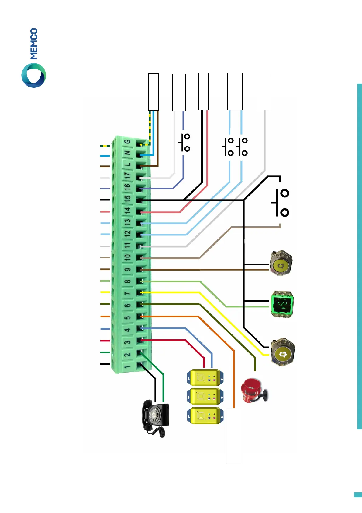
Wiring Diagram
Wiring into a proprietary system?
Whether you are looking to wire into the alarm push button or pictograms in an installed lift, or trying to integrate the Memcom
+
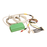
unit into a Lift Monitoring system, we can help. We
have wiring diagrams available to explain how to wire in the unit, pre-connected wire harnesses and a trained technical service team to ensure the installation is clear and simple.
Phone cable colours vary
from site to site, please check
local wiring diagrams
MPS stations (492 021) connected in parallel
0V 0V 0V
Alarm Light Speak Light Alarm Button
End of Alarm
(Optional) N/O
* not required for
453 011AU 24V DC TOC
453 000AU 24V DC only COP
453 010AU 24V DC only TOC
0V
PSTN (GSM Tip)
PSTN (GSM Ring)
MPS
MPS
Siren (Relay)
Siren (Relay)
Alarm Pictogram (+)
Speak Pictogram (+)
Alarm Button
End of Alarm
Common
Lift Status (5-24V DC)
24V DC
0V DC
Service Counter (+)
Service Counter (-)
230V AC Live
Door Filtering (5-24V DC)
230V AC Neutral
Earth
Door Filtering
Lift Status
90-230V AC* Input
Service Counter
12-230V AC/DC
24V DC Input
5-24V DC Input
Common Input
12 & 13
External Siren Power
Supply
Default N/O
See next page for ‘Dual Illuminated Push’ wiring diagram
3