EasyManua.ls Logo

Avital AviStart 3100 User Manual

Avital AviStart 3100
39 pages
To Next Page IconTo Next Page
Page #1 background imageLoading...
Page #1 background image
© 2000 Directed Electronics, Inc. Vista, CA N3100 8-00
®
AviStart 3100
Installation Guide
®

Table of Contents

Question and Answer IconNeed help?

Do you have a question about the Avital AviStart 3100 and is the answer not in the manual?

Avital AviStart 3100 Specifications

General IconGeneral
BrandAvital
ModelAviStart 3100
CategoryCar Alarm
LanguageEnglish

Summary

what is included

wiring quick reference guide

warning! safety first

installation points to remember

finding the wires you need

obtaining constant 12V

How to locate a constant 12V power source in the vehicle.

finding the starter wire

How to locate the vehicle's starter wire using a multimeter.

finding the 12V switched ignition wire

How to locate the 12V switched ignition wire in the vehicle.

finding the accessory wire

How to locate the accessory wire for climate control.

finding a (+) parking light wire

How to locate the vehicle's parking light wire.

finding the tachometer wire

How to locate the vehicle's tachometer wire using a multimeter.

primary harness (H1) wiring diagram

remote start ribbon harness wiring diagram

heavy gauge relay satellite wiring diagram

remote start harness (H2) wiring diagram

primary harness (H1) wire connection guide

H1/1 BLACK (-) chassis ground connection

How to properly connect the chassis ground wire.

H1/2 WHITE/BLUE (-) activation input

How to connect the activation input wire.

H1/3 LIGHT GREEN/BLACK (-) factory security disarm/special accessory output

How to connect the factory disarm/accessory output wire.

H1/4 YELLOW (+) ignition output to RF system

H1/5 WHITE (-) light flash output

H1/6 GRAY/BLACK (-) diesel wait-to-start bulb input

H1/7 LIGHT GREEN (-) door lock output

H1/8 LIGHT BLUE (-) door unlock output

relay satellite key switch interface wire connection guide

RED (2) (+)12V input for relays

How to connect the 12V input to the relays.

PINK (+) ignition output

How to connect the ignition output wire.

PURPLE (+) starter output

How to connect the starter output wire.

remote start harness (H2) wire connection guide

H2/3 GRAY (-) hood pinswitch input

How to connect the hood pinswitch input.

H2/4 BROWN (+) brake switch input

How to connect the brake switch input.

H2/5 VIOLET/WHITE tachometer input

How to connect the tachometer input wire.

H2/6 BLACK/WHITE neutral safety switch input

neutral safety switch interface

general motors trucks, SUVs, and column shifting passenger cars

Wiring diagram for GM trucks/SUVs/cars NSS interface.

pre-1996 dodge dakota pickups with 2.5 liter motors

Wiring diagram for pre-1996 Dodge Dakota NSS interface.

bypassing GM vehicle anti-theft systems (VATS)

1995 and newer vehicle anti-theft systems (immobilizers)

passlock I and passlock II (PL-1 and PL-2)

Information on Passlock I and II systems.

passkey III (PK-3), transponder-based systems

Information on Passkey III and transponder systems.

optional anti-grind relay

door lock wiring guide

type A: (+) 12V pulses from the switch to the factory relays

How to interface with Type A door lock systems.

type C: reversing polarity

How to interface with Type C reversing polarity door lock systems.

type G: positive (+) multiplex

How to interface with Type G positive multiplex door lock systems.

type H: negative (-) multiplex

How to interface with Type H negative multiplex door lock systems.

internal programming jumper

digital tach threshold on/off

How to set the digital tach threshold using the jumper.

plug-in program switch

transmitter/receiver learn routine

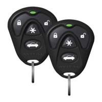
How to add transmitters to the system.

tach learning

operating settings learn routine

operating settings learn routine

How to change programmable operating settings of the unit.

features menu

feature descriptions

Detailed explanation of each programmable feature.

shutdown diagnostics

shutdown diagnostics

How to enter diagnostic mode and interpret shutdown codes.

timer mode

timer mode

How to use the timer mode for scheduled engine starts.

safety check

safety check

Procedures to verify safe installation and operation.

troubleshooting

troubleshooting

Common problems and their solutions.

Related product manuals