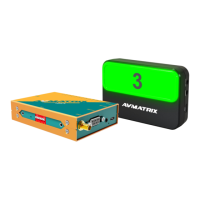
The AVMATRIX TS3019 is a wireless tally system designed to provide real-time broadcast position information to camera operators, hosts, and other related personnel. It indicates the current broadcast position with a red light and the upcoming position with a green light. This system is suitable for various live broadcast activities, including interview programs, performances, sports, live weddings, and church events.
Important Technical Specifications
Tally Box Parameters:
- Connections: 1×GPIO, 1×RS-232, 1×RS-485, 1×USB Type-C
- Number of Lamps Supported: Up to 16 tally lamps (12 LED lamp)
- Wireless Distance: Transmission up to 200m (line-of-sight)
- Wireless Connectivity: 433MHz
- Wired Connectivity: RS-485 serial connection
- Application Support: Compatible with video switchers featuring GPIO-tally interfaces such as AVMATRIX, Roland, SONY, NewTek, Panasonic, DataVideo, or tally converter boxes with GPIO like BMD's GPI and tally interface. It also supports vMix via USB-C.
- Power: Working Voltage: 5V, Power Consumption: ≤ 0.2W
- Dimensions (LWD): 104×75.5×24.5mm
- Weight: 327g
Tally Lamp Parameters:
- Connections: 1×USB Type-C, 1×RS-485, TALLY OUT
- Power Supply: 5V USB power supply or 18650 lithium battery (optional)
- Brightness: Supports 4-level adjustable brightness, up to 2000cd/m²
- Battery Operating Time: Up to 9 hours (depending on battery capacity, lamp brightness, and usage environment)
- Power: Working Voltage: 5V; Power Consumption: ≤2.5W; Battery Charging Current: 5V 1A
- Mounting Hole: 1/4 inch hot shoe hole
- Dimensions (LWD): 98.5×65×26.5 mm
- Weight: 90g (without battery)
Environmental Specifications:
- Working Temperature: -20℃~60℃
- Storage Temperature: -30℃~70℃
Accessories:
- Tally Box: 1×power supply (5V 1A), 1×USB2.0 Type-C cable, 1×antenna, 1×GPIO connector
- Tally Lamp: 1×USB2.0 Type-C cable
Usage Features
Tally Box Features:
- Multiple Interfaces: Equipped with GPIO, USB, RS-485, and RS-232 for versatile connectivity.
- Switcher Compatibility: GPIO is compatible with AVMATRIX and other video switchers.
- vMix Compatibility: Supports vMix via USB-C.
- TSL Protocol Support: RS-232/RS-485 interfaces support TSL protocol for Tally input and one-way transmissive control information.
- Wireless and Wired Tally: Supports 433MHz wireless Tally connection and RS-485 wired Tally connection.
- DIP Switch Configuration:
- SW1-2 (Input Interface Selection):
- (1,1): GPIO input
- (1,0): USB-C input
- (0,1): RS-485 input
- (0,0): RS-232 input
- SW3 (RS-485 Input/Output Selection):
- 1: RS-485 input
- 0: RS-485 output (for wired connection to tally lamp)
- SW4 (Control Mode Selection):
- 1: DIP configuration parameters are used.
- 0: Built-in parameters configured by PC software are used (DIP parameters are invalid).
- SW5 (Group Selection):
- 1: Group 1 selected
- 0: Group 2 selected
- Note: Transmitter and receiver of the same group must be set in the same cluster to prevent interference when multiple tally systems operate within a 1km radius. The software can configure up to 8 groups.
- SW6 (USB-C Operating State):
- 1: USB-C interface is in working state.
- 0: USB-C interface is in configuration state (for connecting to a computer to control software configuration parameters).
Tally Lamp Features:
- Power Options: Can be powered by Micro-USB or an 18650 li-ion battery.
- Dual Indicators: Both front and rear indicators with 4-level adjustable brightness (up to 2000cd/m²).
- Status Display: Visible signal strength and battery status indicators.
- Signal Strength: Green (strong), Yellow (moderate), Red (weak).
- Power Indication: Green (sufficient), Yellow (average), Red (low). Flashes during charging, steady green when fully charged.
- Mounting: 1/4 inch hot shoe for easy installation.
- PTZ Camera Control: Supports remote PTZ camera control via RS-232/RS-485.
- DIP Switch Configuration:
- DIP1 SW 1-4 (Tally Lamp Number): Sets the number of the Tally lamp, corresponding to the Tally input channel.
- DIP2 SW 1 (Connection Type):
- 1: Wireless connection (receives tally information from the tally box transmitter).
- 0: Wired connection (lights up via RS485 connection to tally box).
- DIP2 SW2 (Control Mode Selection):
- 1: DIP configuration parameters are used.
- 0: Built-in parameters configured by PC software are used (DIP parameters are invalid).
- DIP2 SW3 (Group Selection): Sets the group of the tally lamp.
- DIP2 SW4: Reserved key, no function.
Operation Instructions:
- Wireless Tally Connection (Video Switcher): Connect the tally box GPIO to the video switcher. The tally box wirelessly transmits signals to multiple tally lamps.
- Wireless Tally Connection (vMix): Connect the tally box via USB to a PC running vMix. Configure the tally box input to USB-C (SW1:1, SW2:0). Use the Device Manager to identify the COM port. In vMix settings, configure Tally Lights, setting PreviewPIN and ActivePIN for each lamp. Double-click each input in vMix, select Tally Lights, choose the COM port, and assign the Tally Number corresponding to the input source.
- Wired Tally Connection: Connect the tally box GPIO to the video switcher. The tally box connects to the tally lamp via RS-485.
- Remote Serial Control (PTZ Camera): The tally box can connect to a PTZ controller via RS-485/RS-232 and transmit control signals to a PTZ camera via RS-485, with a tally lamp also connected to the RS-485 line.
Maintenance Features
- Safety Precautions:
- Avoid placing the unit on unstable surfaces to prevent falling or damage.
- Operate only on the specified supply voltage.
- Disconnect power by pulling the connector, not the cable.
- Do not place heavy or sharp objects on the power cord; regularly check for wear or damage to prevent fire/electrical shock.
- Do not operate in hazardous or explosive atmospheres.
- Avoid using near water or allowing liquids, metal pieces, or foreign materials to enter the unit.
- Handle with care during transit; use original packing materials or adequate alternatives.
- Do not remove covers, panels, or casing with power applied. Internal servicing should only be performed by qualified personnel.
- Turn off the unit and disconnect everything if an abnormality or malfunction occurs before moving.
- Documentation: Refer to the manual for the PVS0615U video switcher for comprehensive operation details. Keep the manual handy for future reference.
- Product Improvement: Specifications may change without notice due to continuous product improvement efforts.