8 Cyclades ACS 6000 Advanced Console Server Installation/Administration/User Guide
Connecting the Hardware
ACS console server connectors
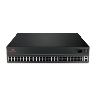
The following figure shows the connectors on the front of the ACS 6000 console server.
Figure 2.2: Front of the Console Server with PC Card Slots and LEDs (ACS 6032 Console Server Shown)
Table 2.1: Connectors on the Console Server Front
Number Description
1 USB connector. Supports the following USB devices: modem, wireless modem, storage and
USB hub.
2 LEDs. See Table 2.2.
3 PC card slots. Supports modem (wireless V.92), Ethernet, Fast Ethernet and storage device
PC cards.
Table 2.2: LEDs on the Console Server Front
Label Description
PWR/CPU Blue
• Blinks - During unit boot
• Solid - During operation
• Off - Power is off
ETH 0/ETH 1 • Amber - Link at 10BaseT speed
• Yellow - Link at 100BaseT speed
• Green - Link at 1000BaseT speed
• Off - No link/cable disconnected/Ethernet fault
AUX/MODEM Dual LED: Yellow on top, green on bottom
• Yellow - DTR/DCD activity
• Green - TXD and RXD activity
• Off - No activity
[One LED for each serial port] Green
• Blinks - Ready, with activity
• Solid - Ready
• Off - Not ready
 Loading...