ANHANG 6 PINBELEGUNG
60
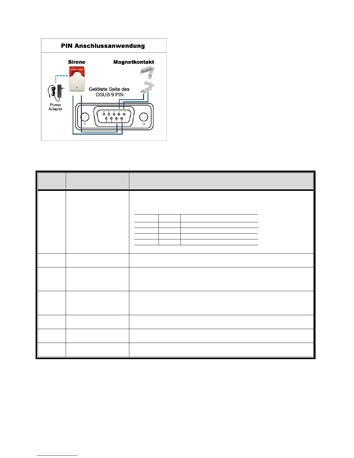
‧ Beim 4 CH Modell
Sirene:
Wenn der DVR durch einen Alarm oder eine
Bewegungserkennung ausgelöst wird, wird COM
mit NO verbunden und die Sirene und Lichtsignale
werden ausgelöst.
Magnetkontakt:
Wenn der Magnetkontakt öffnet, wird der Alarm
ausgelöst und die Aufnahme beginnt.
* Der oben abgebildete D-Sub Anschluss ist optional.
POL FUNKTION BESCHREIBUNG
1~4
ALARMEINGÄNGE
Verbinden Sie ALARMEINGANG (PIN1 - 4) und den GND (PIN5)
Anschluss mit Kabeln. Wenn ein Alarm ausgelöst wird, startet der DVR
die Aufzeichnung und das Signal ertönt.
POL Alarm Entsprechender Videokanal
PIN 1 1 CH1
PIN 2 2 CH2
PIN 3 3 CH3
PIN 4 4 CH4
*
5
MASSE
ERDUNG
6
EXTERNER ALARM
COM
Im Normalbetrieb ist COM von NO getrennt. Bei jeglicher Alarmauslösung
wird COM jedoch mit NO verbunden.
Achtung: Maximale Belastung: 24 VDC, 1 A.
7
Externer Alarm NO
Im Normalbetrieb ist COM von NO getrennt. Bei jeglicher Alarmauslösung
wird COM jedoch mit NO verbunden.
Achtung: Maximale Belastung: 24 VDC, 1 A.
8
RS485-A
Nur für ausgewählte Modelle
9
RS485-B
Nur für ausgewählte Modelle
10~11
MASSE
ERDUNG