•
The device must be operated according to its intended use and within the performance limits specied on the
nameplate.
The connection of the device to the xed electrical system must be made with NYM-O 2x1.5 mm² (H07V-K
2x1.5 mm²) cables with a maximum outside diameter of 8 mm.
•
Do not use the fan to handle the air with the following content:
- viscous contaminants prone to deposition in the fan,
- corrosive contaminants which may degrade the fan,
- ammable contaminants, including gas, vapours, mists or particulates which may form explosive mixtures
with air.
•
The device is equipped with ball bearings that are designed for a minimum operating life of 30,000 hours in S1
duty cycle at the maximum power output and the maximum ambient temperature.
•
The control system must prevent extremely frequent power cycling.
Transport and storage
•
Keep the fans in their original packaging in a dry, sheltered room.
•
The transport and storage ambient temperature limits are -20 °C to +40 °C.
•
Protect against impact and shocks. Transport the fan in its original packaging
•
If the storage time exceeds 1 year, the motor bearings of the fan must be tested by turning the fan rotor by
hand before installation. The fan rotor must run smoothly.
• Dispose of the fan at the end of its operating life strictly in accordance with environmental protection and
waste management laws.
•
Should it occur, damage caused by improper transport, handling, storage or commissioning will be
demonstrated and is not on warranty.
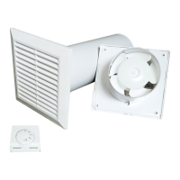
ACCESSORIES
Items of equipment:
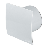
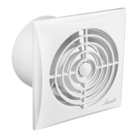
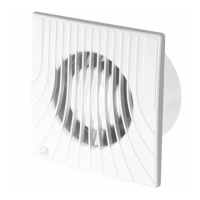
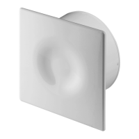
- an exhaust fan (model WAB100)
- a room thermostat
- a section of ventilation duct (Ø 100 mm, length 300 mm)
- a ventilation grille
OPERATING PRINCIPLE
A properly programmed thermostat starts the exhaust fan, by means of which warm air will be supplied to an
adjacent (adjoining) room. The fan will switch o when the temperature drops in the room with a heat source.
INSTALLATION
The device shall only be installed, connected to electrical mains and commissioned for
use by qualied personnel in accordance with applicable laws !
Installation process
•
Precise where the fan will be installed.
•
Prepare power supply cables. Use NYM-O 2x1.5 mm² (H07V-K 2x1.5 mm²) with a maximum outside diameter
of 8 mm.
NOTE: Make sure that the power supply cable is not live before starting work.
•
Measure and make a hole for the unit duct (7) in the wall.
•
Measure and make holes for the fan, grille and thermostat mounting studs.
•
Remove the fan and grille from the duct.
•
Slide the duct into the hole in the wall.
•
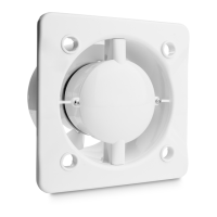
Remove the front clip-on panel (1) of the fan.
•
Remove the fan cover (3) xed with the screw (2).
EN
9