3.2.1 - MOUNTING THE LR-3000 READER
• Keep the reader assembled. Do not remove the aluminum plate behind the reader. Do not drill holes through the aluminum plate. Do
not remove the plastic cover of the reader. Do not tighten or loosen the screws through the cover. This preserves your Warranty.
• Attach the LR-MB mounting bracket to the reader's metal plate using 2 screws (1/4"- 20, supplied).
• Inspect the installation space. The reader may be mounted on any material including metal, but there must be open space in front of
the reader and to its sides. For best results, clear line of sight is needed between with the reader's effective RF field and the credential's
location.
• Measure the mounting height. It must relate to the location of the credentials when they are read in the desired read zone. For
passenger vehicles it is typically at a height of 6-8 feet.
• Be aware of the environment. Aim neighboring readers so that their effective RF fields do not overlap.
• Fasten the reader's adjustable bracket or housing to the pole, post, pedestal, wall, beam or ceiling.
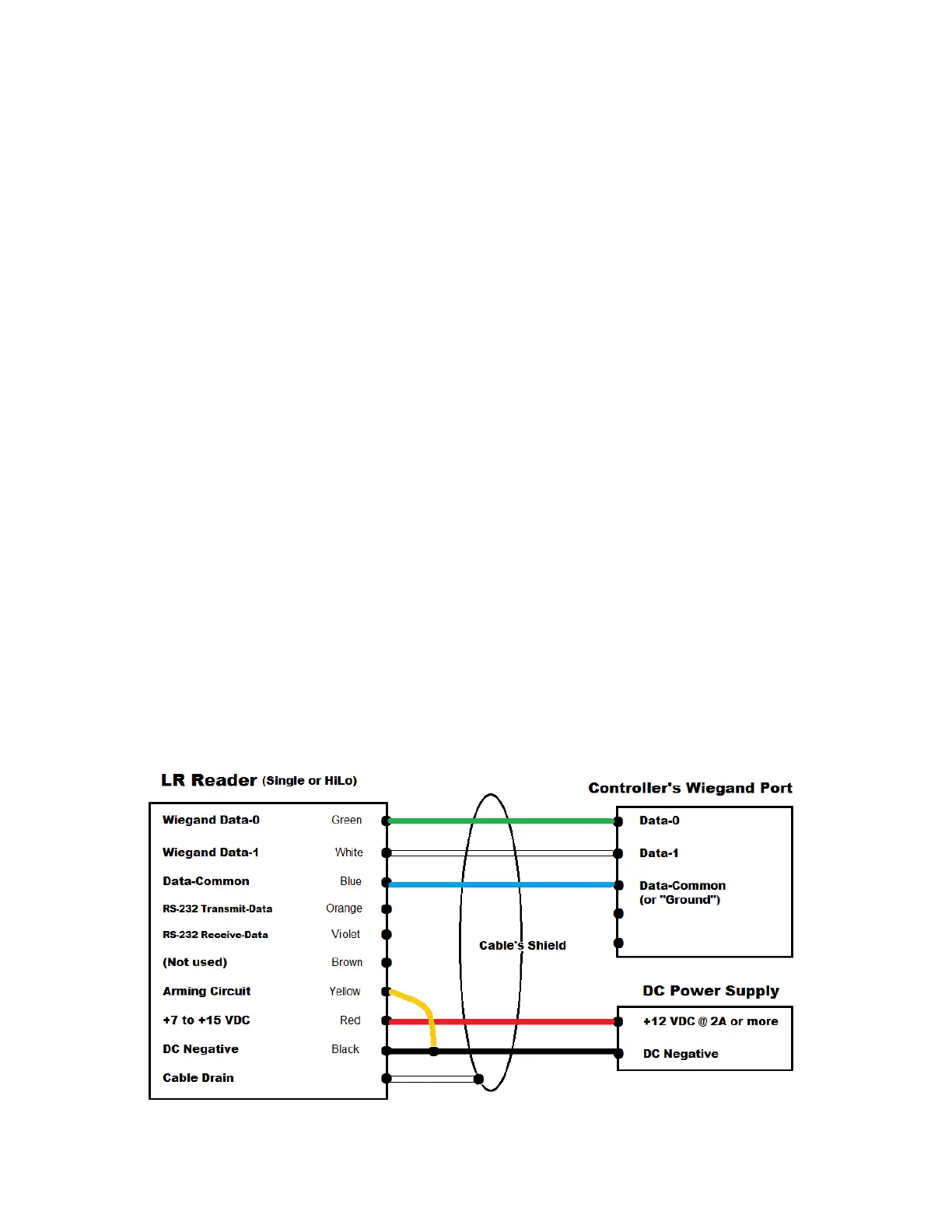
3.2.2 - WIRING THE READER (FOR WIEGAND INTERFACE)
The cable between the LR-3000 reader and the access control panel should be (see complete specs in Section 1.2)
• 5 conductors for data & power • Stranded Wire • High 100% shielded
• 18 gauge for 2 power wires: • Multi conductor (not twisted pair) • High quality
• 22 gauge for 3 Wiegand data wires • Color-coded insulation • Maximum length — 100ft
1. From reader to power supply — Black wire for DC negative (first connection) Each reader needs its own dedicated power supply. (see
specifications in Section 1.2.4)
2. Arming circuit — if you are not using a ground loop system, connect the yellow wire to the black wire at the reader permanently.
For control of the reader's RF transmission by a vehicle sensor, connect the yellow wire to the relay contacts of the vehicle sensor. To
disarm the reader (no RF transmission), do not connect yellow wire.
3. From reader to panel's Wiegand input port — green wire to Data-0, white wire to Data-1, and blue wire to Data-Common. For Data-
Common, use a terminal with this name if available. If not, use this reader port's "Common" or "Ground" terminal. You may wire
the blue to where the black wire goes/ground port would be for a 125 kHz reader.
4. Drains for shields — remove the insulation from the grey wire, exposing the shielded cable. Tie the reader's bare silver wire to the
shields of the power and data cables. Do not ground the drain.
5. Grounds —the LR-3000 and its power supply have no ground connection. Do not connect black, blue and drain wires together.
6. Unused wires — keep the reader's orange wire available to connect the LR-Sounder during set-up and testing. Cap the unused violet and
brown wires separately.
7. Testing — while the cable terminations and junctions are still accessible, test the system for full function and performance. Then seal the
terminations.
Figure 2 Wiring for LR-3000 Installation


 To Next Page