EasyManua.ls Logo

Awntech RN22 - Mounting the Awning; Awning Mounting Specifications; Marking and Installing Brackets; Securing the Awning Frame

Awntech RN22
10 pages
Print Icon
To Next Page IconTo Next Page
To Previous Page IconTo Previous Page
Loading...
Page | 7
MOUNTING THE AWNING:
Step 8) Place awning temporarily in desired location on intended mounting surface. Using a #2 pencil,
mark the wall along the inside of the frame and then remove awning.
Model
Space Between
TB and P
Height w/
Valance
Projection
Model
Space Between
TB and P
Height w/
Valance
Projection
RN22
31
31
24
NY1618
22
22
18
CN32
44
44
24
NY1624
22
22
24
CN33
44
44
36
NY1630
22
22
30
CN34
44
44
48
NY1818
24
24
18
CN43
56
56
36
NY1824
24
24
24
CN44
56
56
48
NY1830
24
24
30
EN2442
24
24
42
NY2430
31
24
30
EN12
12
12
24
NY2436
31
31
36
EN1836
18
18
36
NY3024
37
37
24
EN1230
12
12
30
NY3030
37
37
30
EN1030
16
16
30
NY3036
37
37
36
EN23
24
24
36
NY3048
38
38
48
EN24
24
24
48
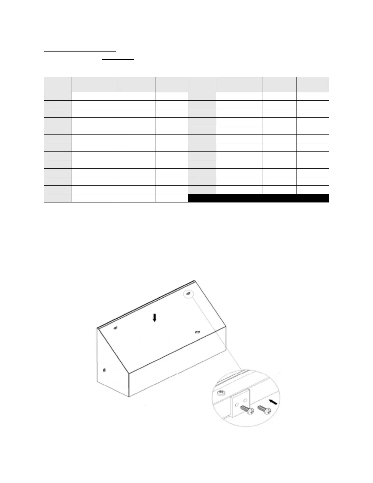
Step 9) Using the marks on the wall, install two (2) Z-brackets into desired mounting location to hold Top
Bar (TB).
Step 10) Drop Top Bar (TB) into mounted Z-brackets and check the fit. Once position is satisfactory, use
Power Drill to attach Top Bar (TB) to Z-brackets with self-tapping screws. After Top Bar (TB) is secured to
the mounting surface, install one (1) Z-bracket on the inside of each Back Bar (BB) with self-tapping
screws. NOTE: There are no pre-drilled holes for Z-brackets, they may be placed anywhere along the
surface of the Top Bar (TB) and Back Bars (BB) to accommodate your mounting surface’s stud location.

Related product manuals