3603 Burron Avenue, Saskatoon, SK S7P 0E4 Ph: (306) 651-1815 Fax: (306) 651-2293
email: sales@axiomind.com website: www.axiomind.com
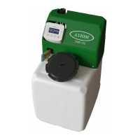
DMF Series Solution Feeder
Installation, Operation, & Maintenance Instructions
- Français page 11 -
Installation Procedure
1) Set system feeder on a secure and level base or on the provided wall bracket.
2) If mounting on the wall, the cardboard cut-out on the side of the DMF box may be used to locate the
screw holes for the wall bracket.
3) Ensure the wall bracket is level and fastened securely to the wall.
4) HANG AND FILL TANK PRIOR TO MAKING SYSTEM CONNECTION. This helps to
ensure that the tank is securely seated on the mounting bracket
Startup Procedure
1) Close isolation valve between feeder and system connection point
2) Fill reservoir, turn valve on feeder to mix/purge and plug in
3) Ensure pump is cycling fluid through reservoir (primed)
4) Simultaneously turn valve to run and open isolation valve to system
Scan the QR code to the left, search for Axiom Industries Ltd. on
YouTube, or use the link below to view a list of instructional
videos on the DMF series system feeders:
https://www.youtube.com/watch?v=tmWsw0clEng&list=UU3IhT
10cEPKmm_S-HlGcbNw