Specifications
Powersource
Maxpowerat12VDCMaxpowerat24VDC
DCIN
1600mA800mA
PoE1200mA600mA
NO NO
NO
TICE TICE
TICE
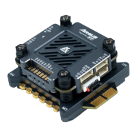
Ifthelockisnon-polarized,werecommendyoutoaddanexternalybackdiode.
Auxiliaryconnector
Usetheauxiliaryconnectorwithexternaldevicesincombinationwith,forexample,motiondetection,eventtriggering,andalarm
notications.Inadditiontothe0VDCreferencepointandpower(DCoutput),theauxiliaryconnectorprovidestheinterfaceto:
Digitalinput-Forconnectingdevicesthatcantogglebetweenanopenandclosedcircuit,forexamplePIRsensors,door/window
contacts,andglassbreakdetectors.
Digitaloutput-ForconnectingexternaldevicessuchasrelaysandLEDs.ConnecteddevicescanbeactivatedbytheVAPIX®
ApplicationProgrammingInterfaceorfromtheproduct’swebpage.
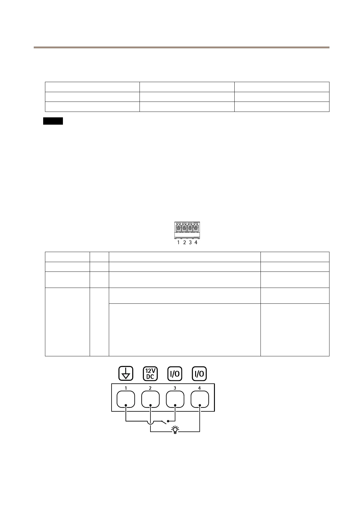
4-pinterminalblock
FunctionPinNotes
Specications
DCground
1
0VDC
DCoutput
2
Canbeusedtopowerauxiliaryequipment.
Note:Thispincanonlybeusedaspowerout.
12VDC
Maxload=50mAintotal
Digitalinput–Connecttopin1toactivate,orleaveoating
(unconnected)todeactivate.
0tomax30VDC Congurable
(InputorOutput)
3–4
Digitaloutput–Internallyconnectedtopin1(DCground)when
active,andoating(unconnected)wheninactive.Ifusedwithan
inductiveload,e.g.,arelay,connectadiodeinparallelwiththe
load,toprotectagainstvoltagetransients.EachI/Oiscapableof
driving12VDC,50mA(max)externalload,ifinternal12VDC
output(pin2)isused.Inthecaseofusingopendrainconnections
incombinationwithanexternalpowersupply,thentheI/Oscan
manageDCsupplyof0–30VDC,100mA.
0tomax30VDC,opendrain,
100mA
1
DCground
2
DCoutput12V
3
I/Oconguredasinput
27