AXISF41MainUnit
HardwareOverview
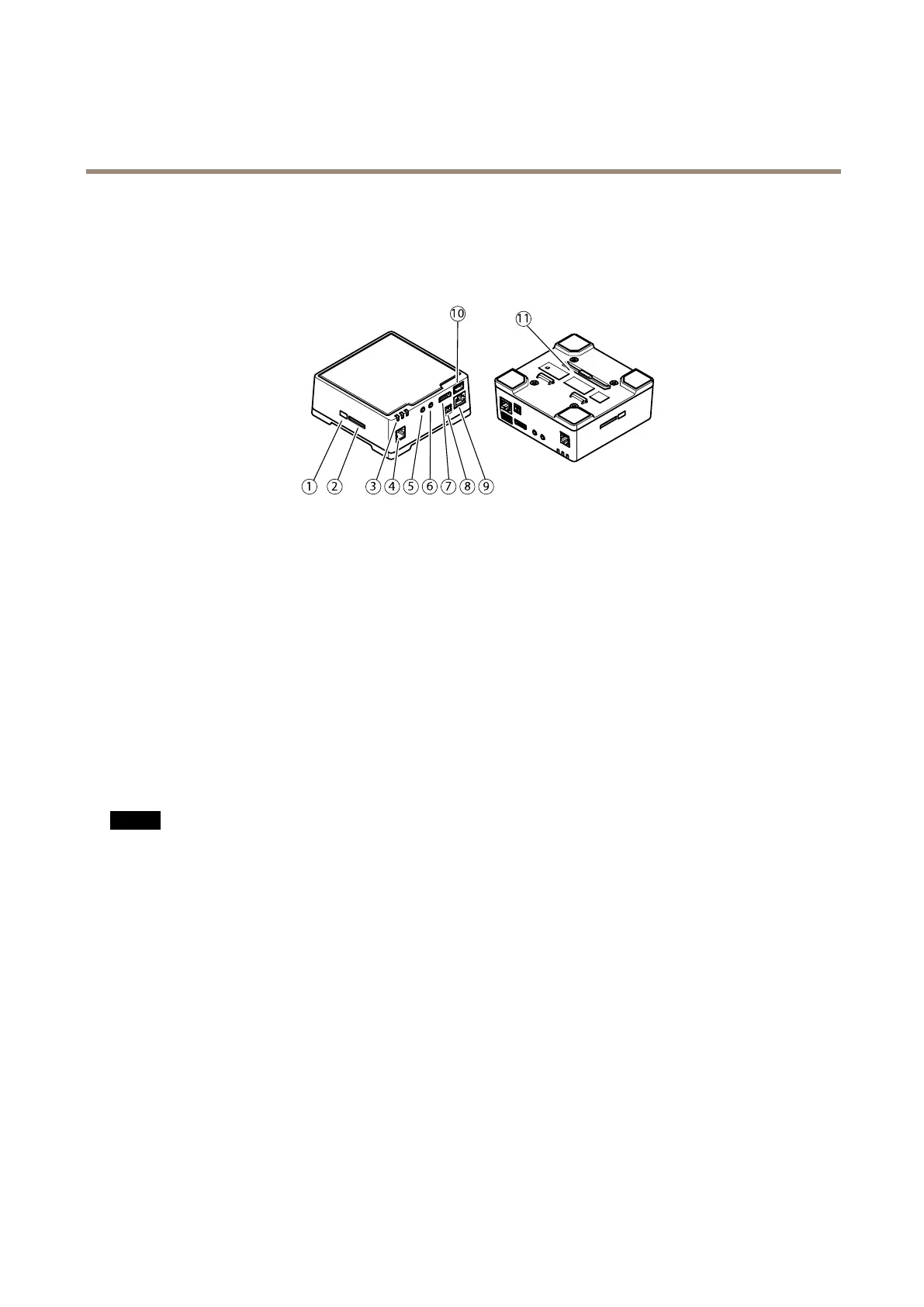
HardwareOverview
Forspecicationsofthehardwarecomponents,seeTechnicalSpecicationsonpage64.
1.
Controlbutton
2.
SDcardslot
3.
LEDs(Power,Status,Network)
4.
RJ12connector
5.
Audioin
6.
Audioout
7.
I/Oconnector
8.
Powerconnector
9.
Networkconnector(PoE)
10.
RS232connector
11.
Plasticbottomplate
ConnectorsandButtons
NetworkConnector
RJ45EthernetconnectorwithPoweroverEthernet(PoE).
NO NO
NO
TICE TICE
TICE
Theproductshallbeconnectedusingashieldednetworkcable(STP).Allcablesconnectingtheproducttothenetworkshall
beintendedfortheirspecicuse.Makesurethatthenetworkdevicesareinstalledinaccordancewiththemanufacturer’s
instructions.Forinformationaboutregulatoryrequirements,seeElectromagneticCompatibility(EMC)onpage2.
I/OConnector
Usewithexternaldevicesincombinationwith,forexample,tamperingalarms,motiondetection,eventtriggering,andalarm
notications.Inadditiontothe0VDCreferencepointandpower(DCoutput),theI/Oconnectorprovidestheinterfaceto:
•Digitaloutput–ForconnectingexternaldevicessuchasrelaysandLEDs.Connecteddevicescanbeactivatedbythe
VAPIX®ApplicationProgrammingInterface,outputbuttonsontheLiveViewpageorbyanActionRule.Theoutputwill
showasactive(shownunderSystemOptions>Ports&Devices)ifthealarmdeviceisactivated.
•Digitalinput–Analarminputforconnectingdevicesthatcantogglebetweenanopenandclosedcircuit,forexample:
PIRs,door/windowcontacts,glassbreakdetectors,etc.Whenasignalisreceivedthestatechangesandtheinputbecomes
active(shownunderSystemOptions>Ports&Devices).
6