46
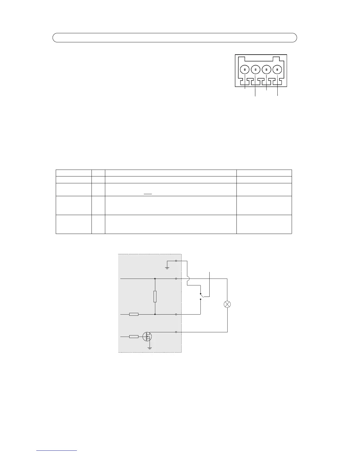
AXIS P1346/-E/AXIS P1347 - Unit connectors
I/O terminal connector - Used in applications for e.g. motion detection, event triggering,
time lapse recording and alarm notifications. In addition to an auxiliary power and a GND
pin, it provides the interface to:
• 1 digital output - For connecting external devices such as relays and LEDs. Con-
nected devices can be activated by the VAPIX® Application Programming Interface,
output buttons on the Live View page or by an Event Type. The output will show as
active (shown under Events > Port Status) if the alarm device is activated.
• 1 digital input - An alarm input for connecting devices that can toggle between an
open and closed circuit, for example: PIRs, door/window contacts, and glass break detectors. When a signal is received
the state changes and the input becomes active (shown under Events > Port Status).
Notes:
• The I/O connector on AXIS P1346-E is connected to the housing electronics (fan/heater) at delivery, see illustration on
page 5, and will trigger an input port event to indicate a fan or heater error when activated. See Events, on page 29,
for information on how to set up an event.
• For information on how to connect external devices, refer to the Installation Guide supplied with the product.
The following connection diagram gives an example of how to connect an auxiliary device to AXIS P1346/-E/AXIS P1347.
Function Pin Notes Specifications
GND 1 Ground
3.3 V DC Power 2 Can be used to power auxiliary equipment.
Note: This pin can only
be used as power out.
Max load = 50 mA
Digital Input 3 Connect to GND to activate, or leave floating (unconnected) to
deactivate.
AXIS P1346-E: Connected to housing electronics at delivery.
Min. input = -40 V DC
Max. input= +40 V DC
Digital Output 4 Uses an open-drain NFET transistor with the source connected to
GND. If used with an external relay, a diode must be connected in
parallel with the load, for protection against voltage transients.
Max. load =100 mA
Max. voltage = + 40 V DC