AXISP13-ESeries
ConnectionDiagrams
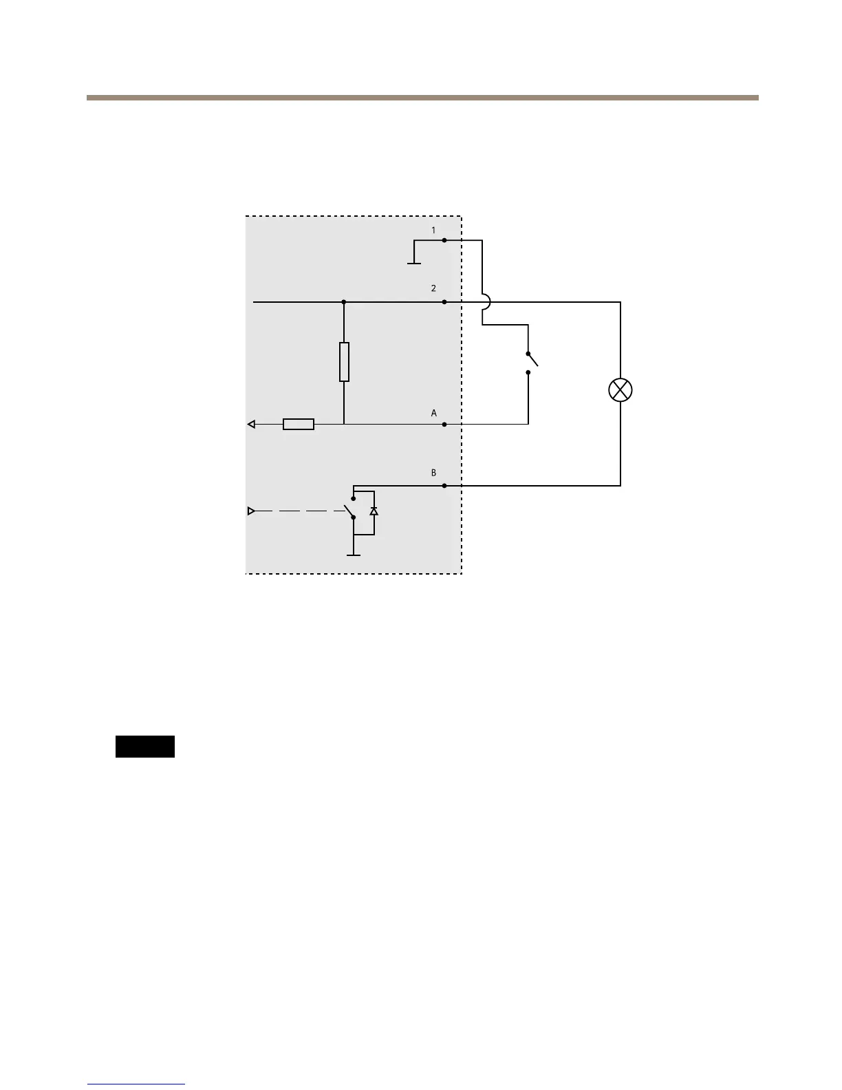
I/OConnector
1
0VDC(-)
2
DCoutput12V,max50mA
A
I/Oconguredasinput
B
I/Oconguredasoutput
InstalltheHardware
NO NO
NO
TICE TICE
TICE
•Duetolocalregulationsortheenvironmentalandelectricalconditionsinwhichthe
productistobeused,ashieldednetworkcable(STP)maybeappropriateorrequired.
Allcablesconnectingtheproducttothenetworkandthatareroutedoutdoorsorin
demandingelectricalenvironmentsshallbeintendedfortheirspecicuse.Makesurethat
thenetworkdevicesareinstalledinaccordancewiththemanufacturer’sinstructions.
Forinformationaboutregulatoryrequirements,seeRegulatoryInformationonpage2
•Becarefulnottoscratch,damageorleavengerprintsonthewindowbecausethiscould
decreaseimagequality.
TheAxisproductcanbeinstalledwiththecablesroutedthroughoralongthewall.
19