AXISP1365MkIINetworkCamera
Technicalspecifications
ForSDcardrecommendations,seewww.axis.com
Connectors
Networkconnector
RJ45EthernetconnectorwithPoweroverEthernet(PoE).
NO NO
NO
TICE TICE
TICE
Duetolocalregulationsortheenvironmentalandelectricalconditionsinwhichtheproductistobeused,ashieldednetwork
cable(STP)maybeappropriateorrequired.Allcablesconnectingtheproducttothenetworkandthatareroutedoutdoors
orindemandingelectricalenvironmentsshallbeintendedfortheirspecicuse.Makesurethatthenetworkdevices
areinstalledinaccordancewiththemanufacturer’sinstructions.Forinformationaboutregulatoryrequirements,see
ElectromagneticCompatibility(EMC)onpage2.
Audioconnector
TheAxisproducthasthefollowingaudioconnectors:
•Audioin(pink)–3.5mminputforamonomicrophone,oraline-inmonosignal.
•Audioout(green)–3.5mmoutputforaudio(linelevel)thatcanbeconnectedtoapublicaddress(PA)systemoran
activespeakerwithabuilt-inamplier.Astereoconnectormustbeusedforaudioout.
Foraudioin,theleftchannelisusedfromastereosignal.
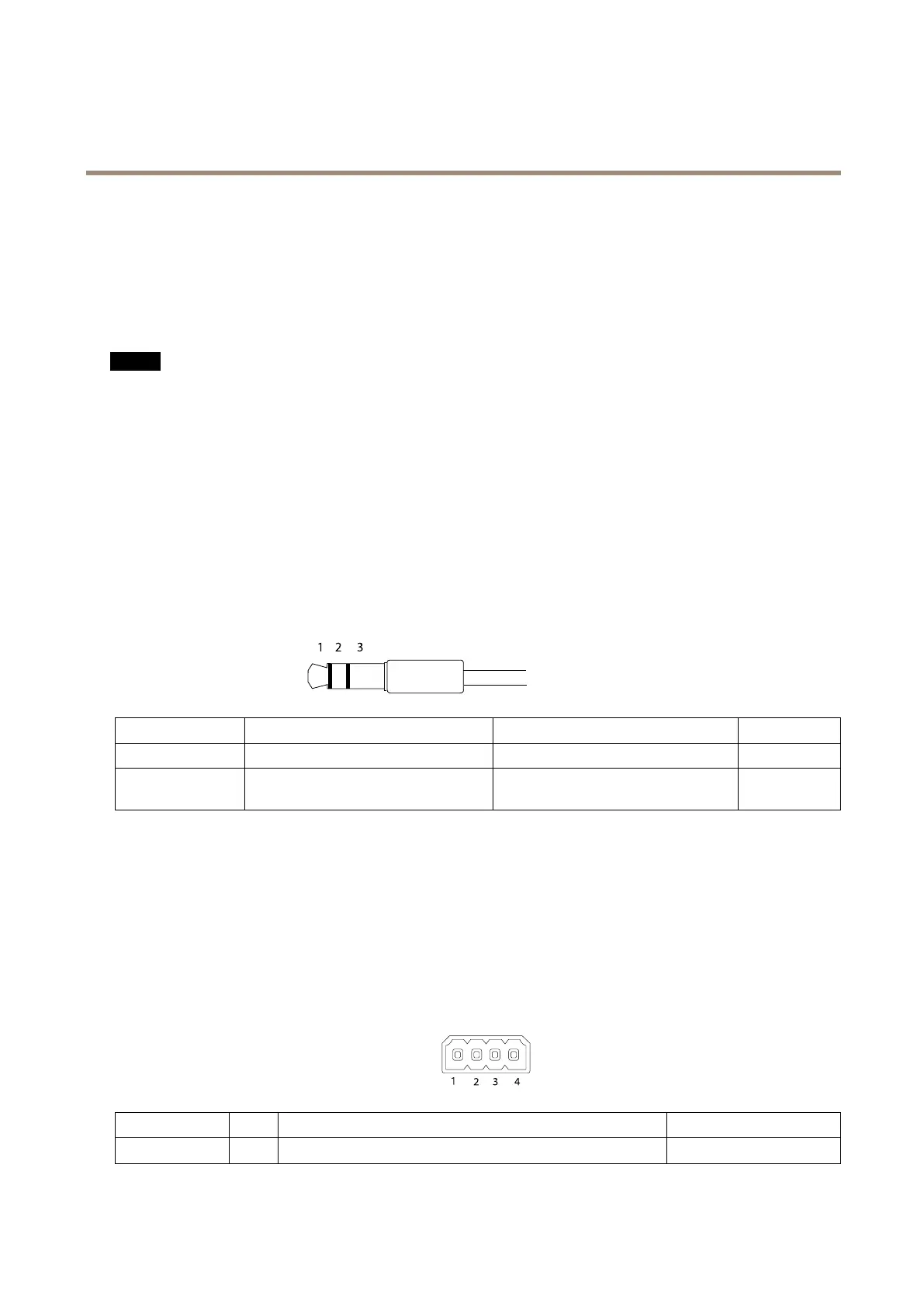
3.5mmaudioconnectors
(stereo)
1Tip2Ring
3Sleeve
AudioInput
Ground
AudioOutput
Lineout,mono(stereoconnector
compatible)
Lineout,mono(stereoconnector
compatible)
Ground
I/Oconnector
Usewithexternaldevicesincombinationwith,forexample,tamperingalarms,motiondetection,eventtriggering,andalarm
notications.Inadditiontothe0VDCreferencepointandpower(DCoutput),theI/Oconnectorprovidestheinterfaceto:
•Digitaloutput–ForconnectingexternaldevicessuchasrelaysandLEDs.Connecteddevicescanbeactivatedbythe
VAPIX®ApplicationProgrammingInterface,outputbuttonsontheLiveViewpageorbyanActionRule.Theoutputwill
showasactive(shownunderSystemOptions>Ports&Devices)ifthealarmdeviceisactivated.
•Digitalinput–Forconnectingdevicesthatcantogglebetweenanopenandclosedcircuit,forexample:PIRs,door/window
contacts,glassbreakdetectors,etc.Whenasignalisreceivedthestatechangesandtheinputbecomesactive(shown
underSystemOptions>Ports&Devices).
4–pinterminalblock
FunctionPinNotes
Specications
0VDC(-)
1
DCground0VDC
73