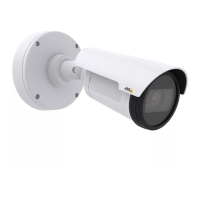
AXISP1425-ENetworkCamera
Technicalspecifications
•Digitaloutput–ForconnectingexternaldevicessuchasrelaysandLEDs.Connecteddevicescanbeactivatedbythe
VAPIX®ApplicationProgrammingInterface,outputbuttonsontheLiveViewpageorbyanActionRule.Theoutputwill
showasactive(shownunderSystemOptions>Ports&Devices)ifthealarmdeviceisactivated.
•Digitalinput–Forconnectingdevicesthatcantogglebetweenanopenandclosedcircuit,forexample:PIRs,door/window
contacts,glassbreakdetectors,etc.Whenasignalisreceivedthestatechangesandtheinputbecomesactive(shown
underSystemOptions>Ports&Devices).
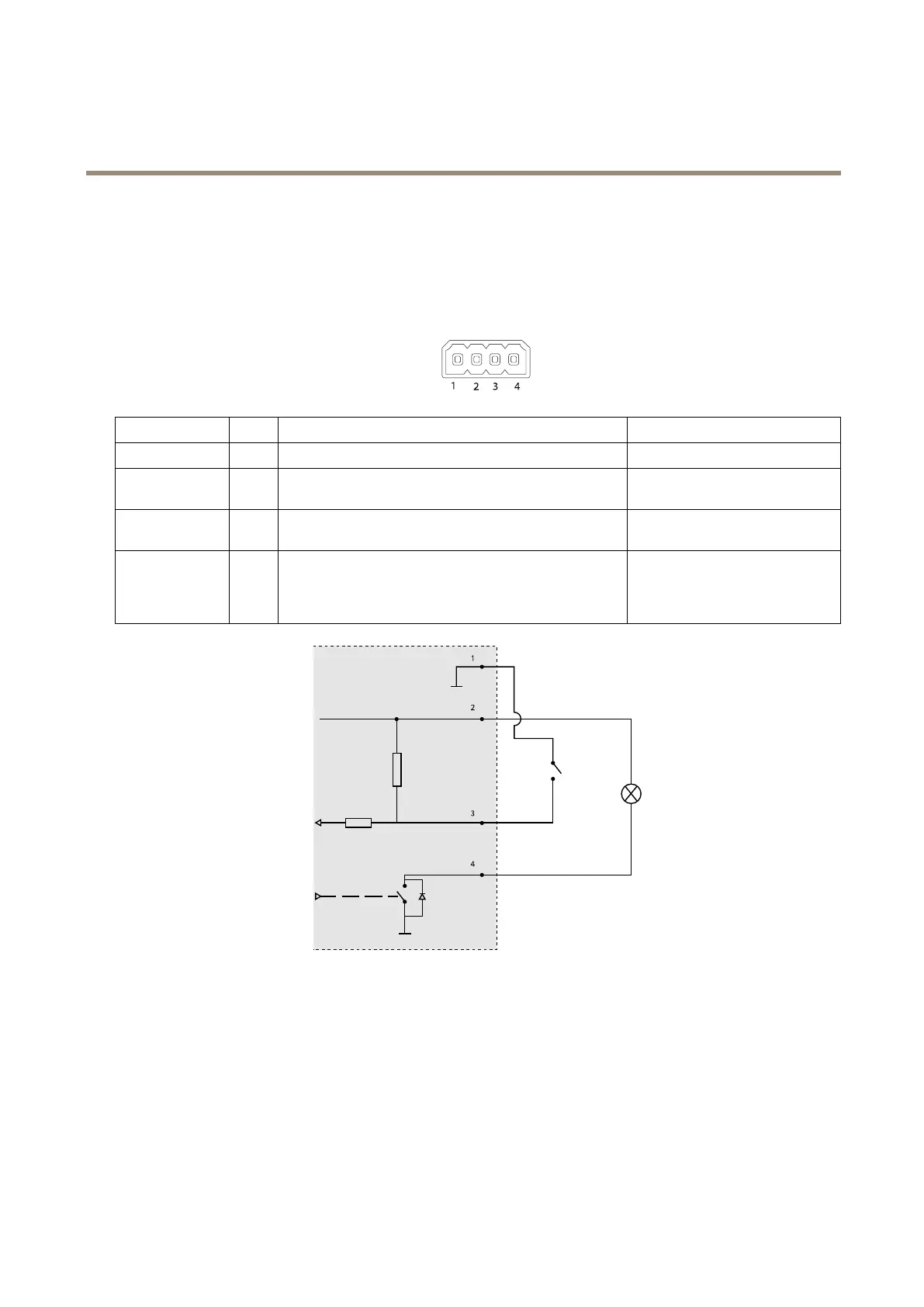
4–pinterminalblock
FunctionPinNotes
Specications
0VDC(-)
1
0VDC
DCoutput
2
Canbeusedtopowerauxiliaryequipment.
Note:Thispincanonlybeusedaspowerout.
12VDC
Maxload=15mA
DigitalInput
3
Connecttopin1toactivate,orleaveoating(unconnected)
todeactivate.
0tomax30VDC
DigitalOutput
4
Connectedtopin1whenactivated,oating(unconnected)
whendeactivated.Ifusedwithaninductiveload,e.g.arelay,
adiodemustbeconnectedinparallelwiththeload,for
protectionagainstvoltagetransients.
0tomax30VDC,opendrain,
100mA
1
0VDC(-)
2
DCoutput12V,max15mA
3
I/Oconguredasinput
4
I/Oconguredasoutput
PerformanceConsiderations
Whensettingupyoursystem,itisimportanttoconsiderhowvarioussettingsandsituationswillaffectperformance.Somefactors
affecttheamountofbandwidth(thebitrate)required,otherscanaffecttheframerate,andsomeaffectboth.Iftheloadonthe
CPUreachesitsmaximum,thiswillalsoaffecttheframerate.
Thefollowingfactorsareamongthemostimportanttoconsider:
63