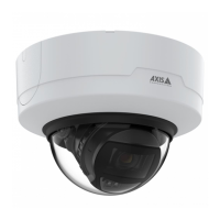
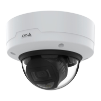
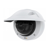
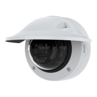
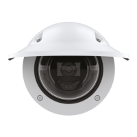
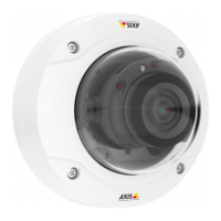
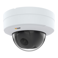
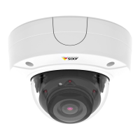
AXISP32DomeCameraSeries
Specifications
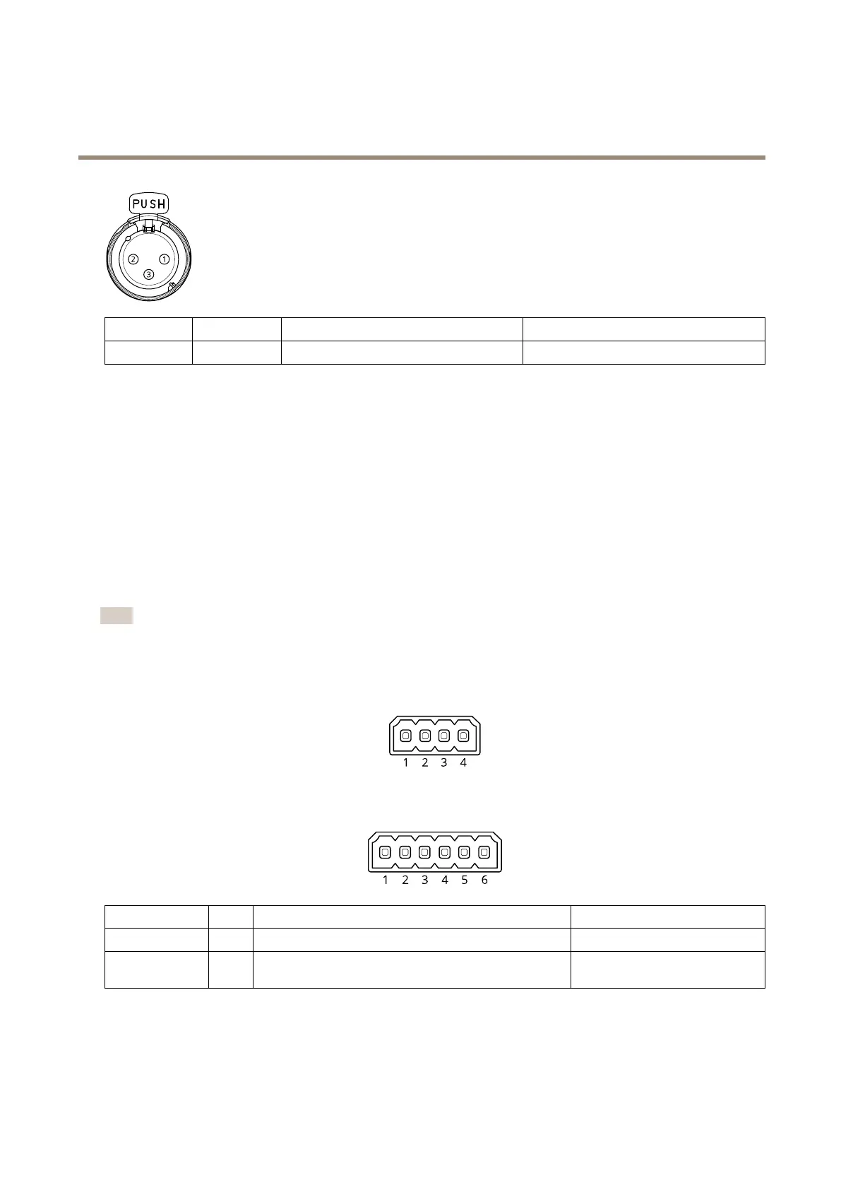
Pin
1
23
Function
Ground
BalancedMicrophoneHot(+)InBalancedMicrophoneCold(-)In
I/Oconnector
UsetheI/Oconnectorwithexternaldevicesincombinationwith,forexample,motiondetection,eventtriggering,andalarm
notications.Inadditiontothe0VDCreferencepointandpower(DCoutput),theI/Oconnectorprovidestheinterfaceto:
Digitalinput-Forconnectingdevicesthatcantogglebetweenanopenandclosedcircuit,forexamplePIRsensors,door/window
contacts,andglassbreakdetectors.
Supervisedinput-Enablespossibilitytodetecttamperingonadigitalinput.
Digitaloutput-ForconnectingexternaldevicessuchasrelaysandLEDs.ConnecteddevicescanbeactivatedbytheVAPIX®
ApplicationProgrammingInterface,troughaneventorfromtheproduct’swebpage.
Adigitallightsensor-Forreceivingavalueoftheambientlightintensityfromanexternallightsensor.Thisisusedtocontrolthe
product’sdayandnightfunctionality.
Note
TheI/Oconnectorisconnectedtothehousing(fan/heater)ondelivery.Incaseofafanorheatererror,aninputsignalwillbe
triggeredinthecamera.Setupanactionruleinthecameratocongurewhichactionthesignalshalltrigger.
4-pinterminalblock
6-pinterminalblock
FunctionPinNotes
Specications
DCground
1
0VDC
DCoutput
2
Canbeusedtopowerauxiliaryequipment.
Note:Thispincanonlybeusedaspowerout.
12VDC
Maxload=25mA
60