15
WHITE
AXMINSTER
W
Assembly Configurations...
Fig 39
Fig 40
Fig 41
Fig 42
Table to Linisher Assembly
Option 1
The table (E) can be repositioned to be used when the linisher is raised in the up-right
position, see instruction below.
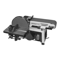
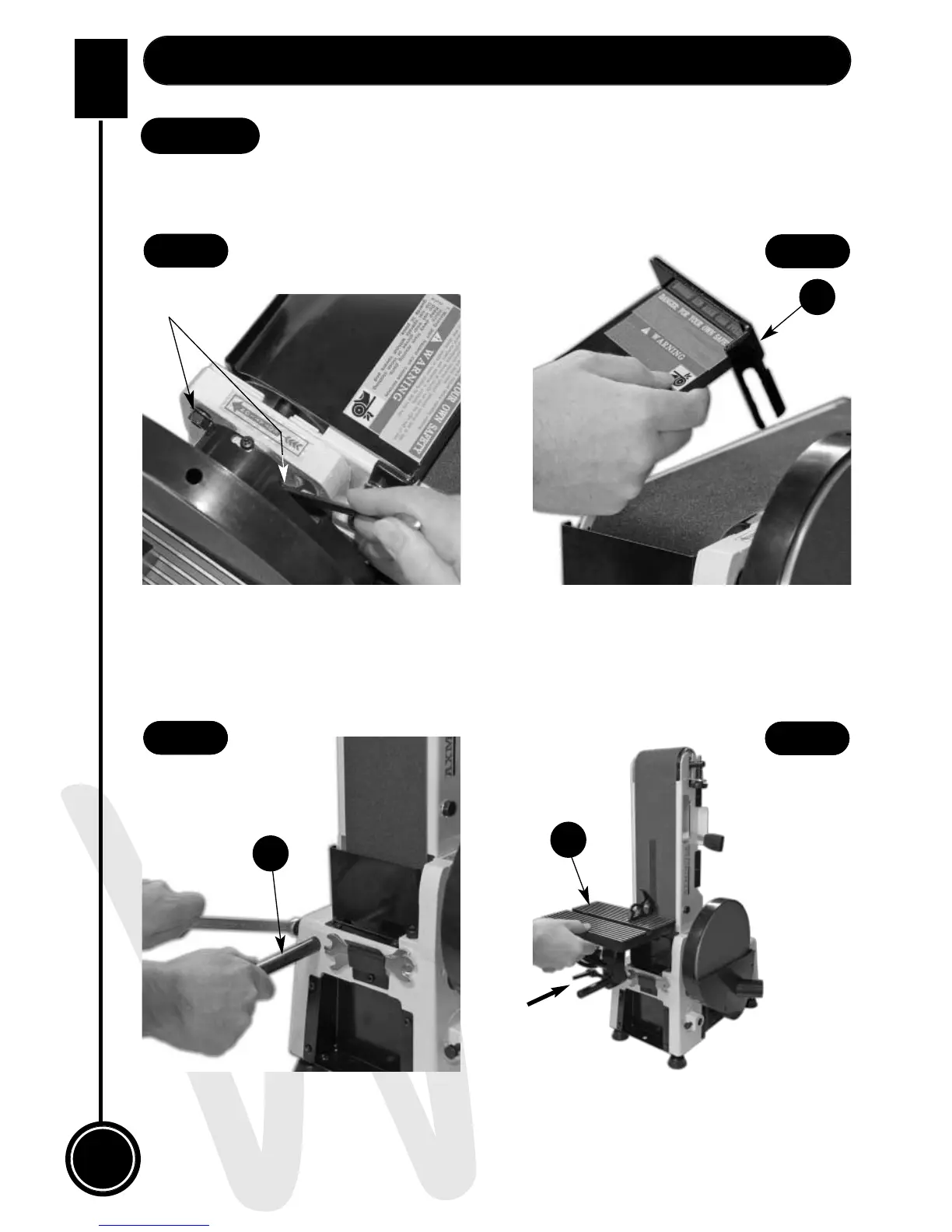
Loosen the linisher’s clamping nuts, see fig 39, remove the workstop plate (H), see fig 40
(refer to step 4) raise the linisher & clamp in place. Loosen the bolt to the side of the sander,
insert the table support rod (D) into the machined hole & tighten using a 14mm spanner
(See figs 40 & 41). Slide the table (H) onto the rod as described on page 13 & tighten using
the lower lift & shift handle (b) (See fig 32).
Place a 90˚ degree square on the table and check that the table (E) is perpendicular to the
belt (See fig 42). If it requires adjustment, loosen the upper lift & shift handle (a), see fig 32
until correct. Re-tighten the lift & shift handle (a).
H
D
E
Clamping nuts