11
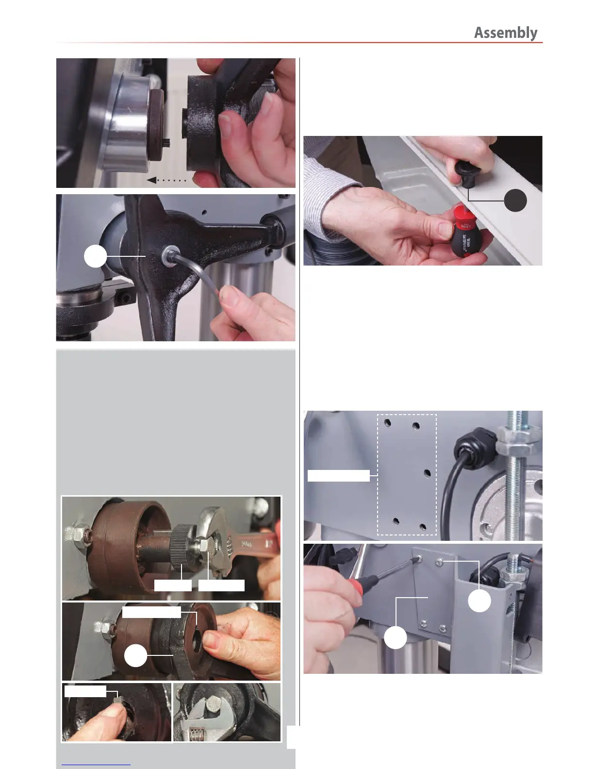
3. Locate the pulley cover knob (13), remove the Phillips screw,
insert the screw through the pre-drilled hole in the pulley cover
and secure the knob in place, see fig 27.
Fig 27
Pulley Cover Knob
9
13
Chuck guard
4. Locate the chuck guard assembly (7), chuck guard mounting
bracket (6) and the four M6 button head Phillips screws (17).
Offer up the four pre-drilled holes in the mounting bracket (6)
with threaded holes to the side of the drill head assembly (3).
Secure in position with the four M6 screws (17), see fig 28-29
NOTE: Make sure the cutout slot in the mounting bracket (6)
is to the top.
Fig 28-29
5. Line up the two holes in the micro switch unit with
threaded holes to the end of the angled bracket (6). Make
sure to introduce the micro switch cable into the cutout slot
in the mounting bracket (6). Secure the micro switch with two
M5 Phillips screws (18), see fig 30-31.
Continues Over....
Threaded holes
6
17
Lever Feed Handle (ATDP20F ONLY)
Locate the lever feed handle (9), remove the centre bolt and
unscrew the centre cap from the raised boss drive shaft,
place safely aside, see fig 24. Remove the square key from
the machined slot on the drive shaft. Mount the handle over
the drive shaft so the square cut out on the handle lines up
with machined slot in the shaft. Replace the square key,
screw on the centre cap and secure the handle in place with
the centre bolt, see fig 25-26.
Fig 24-25-26
Centre cap Centre bolt
9
Key slot cut out
Square key
 Loading...