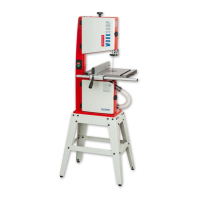
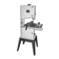
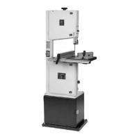
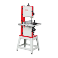
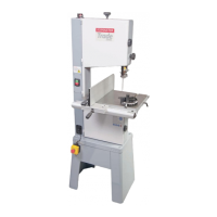
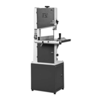
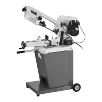
ASSEMBLY
10
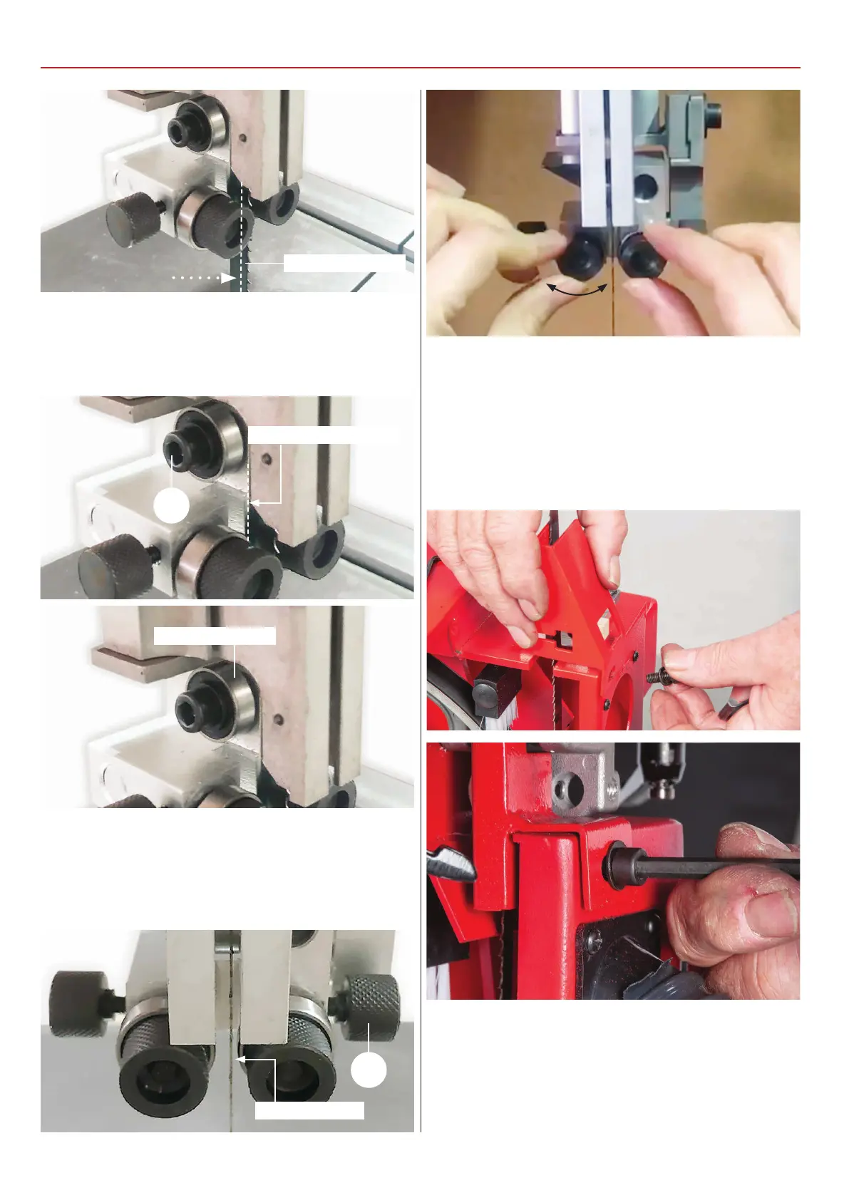
3) Loosen the caphead bolt (B) that clamps the rear thrust
bearing, position the bearing so it’s 1mm behind the blade,
retighten the grub screw, see fig 12-13.
2mm behind blade
Fig 12-13
Rear thrust bearing
1mm behind the blade
B
4) Loosen the two clamping knobs (A) holding the blade guides.
Adjust the guide bearings to approximately 0.5mm clearance
on either side of the blade. Re-tighten the clamping knobs (A),
see fig 14-15.
Fig 14-15
0.5mm clearance
5) Remove the lower blade guide guard and place safely
aside, see fig 16-17.
6) To set the fore and aft position on the lower guide
assembly, loosen the two cap head bolts (B) for models
AW2305B, AW2606B, see fig 18. For model AW1950B loosen
Fig 16-17
the bolt to the under side of the bottom wheel housing, see fig
19. Note you may need to remove the lower wheel brush to
gain access to the bolt, see fig 20. Once complete secure the
assembly.
A
 Loading...