EasyManua.ls Logo

Axpert 3KVA-110V - User Manual

Axpert 3KVA-110V
30 pages
Print Icon
To Next Page IconTo Next Page
Loading...
SERVICE MANUAL
3KVA-110V/120V
2
V201608A
Table of contents
1. General information .............................................................................................................................................. 3
1.1 Getting start ................................................................................................................................................. 3
1.2 Basic topology introduction ....................................................................................................................... 3
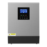
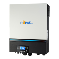
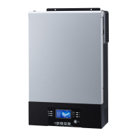
1.3 Inverter family.............................................................................................................................................. 4
1.4 Overview the inverter ................................................................................................................................. 4
1.5 PCB overview.............................................................................................................................................. 5
2. Troubleshooting .................................................................................................................................................... 7
2.1 How to do ..................................................................................................................................................... 7
2.2 Check the fault information ....................................................................................................................... 7
2.3 Fault condition ............................................................................................................................................. 7
2.4 Test step ....................................................................................................................................................... 8
3. Checking and measuring guide .......................................................................................................................... 9
3.1 Check the battery side components ........................................................................................................ 9
3.2 Check the bus side components ............................................................................................................ 16
3.3 Check the buck circuit .............................................................................................................................. 18
3.4 Check the INV full bridge ........................................................................................................................ 20
3.5 Check the PWM SCC board ................................................................................................................... 22
3.6 Check the MPPT SCC board .................................................................................................................. 23
4. Disassembling guide .......................................................................................................................................... 24
4.1 Open the case ........................................................................................................................................... 24
4.2 Remove the control board ....................................................................................................................... 25
4.3 Remove the fans. ..................................................................................................................................... 26
4.4 Remove the MPPT board. ....................................................................................................................... 28
4.5 Remove the main board. ......................................................................................................................... 29
5. Cables connection .............................................................................................................................................. 31

Questions and Answers

Summary

General Information

Getting Started Guide

Manual is a checking and repairing guide for 3KVA-110V/120V model. Requires electrical/electronic background knowledge.

Basic Topology Introduction

Explains the inverter's topology, including solar charger integration for enhanced functionality.

Inverter Family Overview

Inverter Model Specifications

Table detailing parameters for different inverter models based on power rating and solar charger type.

Inverter Hardware Overview

Visual identification of key components of the inverter, including boards and indicators.

PCB Component Identification

MPPT Main Board Layout

Illustrates the main board for MPPT models, highlighting connection points and power supply.

PWM Main Board Layout

Illustrates the main board for PWM models, showing connection points and power supply.

Board-Level Component Identification

Control Board Details

Details the control board, showing connections to various components like LCD, LED, and SCC.

MPPT SCC Board Details

Shows the MPPT SCC board with identified battery and solar connections.

Troubleshooting Guide

Troubleshooting Procedure

Guides users on how to record fault information and proceed when the inverter has issues.

Fault Information Checks

Procedures for testing modes and diagnosing issues based on fault information.

No Display or Not Working Fault

Troubleshooting steps for an inverter that does not start up or show any display.

09 Fault Diagnosis

Diagnosing and resolving '09 fault' indicating a bus soft start failure.

56 Fault Diagnosis

Troubleshooting '56 fault' related to the battery not being detected.

General Fault Conditions

Guidelines for checking for obvious damage on boards during fault diagnosis.

Post-Repair Test Steps

Steps to confirm repair results and inverter reliability after component replacement.

Checking and Measuring Guide

Battery Side Component Checks

Checks for fuse and capacitors on the battery side.

DC;DC MOSFET Checks

Checking DC/DC MOSFETs (Q11/Q17/Q20/Q24 etc.) for resistance and diode characteristics.

Driver Circuit Resistor Checks

Checking specific resistors (R41, R59, etc.) in the driver circuit.

NPN;PNP Transistor Checks

Checking NPN and PNP transistors (Q46-Q49, Q15-Q16) for resistance and diode values.

SOT-89 Power Device Checks

Checking SOT-89 packaged transistors (Q54-Q57, Q50-Q53) for resistance and diode values.

SOT-23 MOSFET Checks

Checking MOSFETs (Q60, Q61) in SOT-23 package for resistance and diode characteristics.

Component U9 Checks

Checking component U9 for resistance values between pins.

Bus Side Component Checks

DC;DC IGBT Checks

Checking DC/DC IGBTs (Q27-Q30) for resistance and diode forward voltage.

Driver Circuit Component Checks

Checking resistors and diodes in the driver circuit for power tubes.

Buck Circuit Checks

Buck MOSFET and Diode Checks

Checking Buck MOSFET (Q32) and Diode (D13) for resistance and diode values.

Buck Driver Circuit Checks

Checking resistors (R125, R124) and diode (D38) in the driver circuit.

INV Full Bridge Checks

INV IGBT Checks

Checking INV IGBTs (QA1, QC1, QB2, QD2) for resistance and diode characteristics.

INV Driver Circuit Checks

Checking resistors and diodes in the driver circuit.

Optocoupler Checks

Checking optocouplers (U1, U2, U3, U4, U12) for resistance values.

PWM SCC Board Checks

PWM SCC MOSFET Checks

Checking MOSFETs (Q63, Q68, Q73, Q7, Q31) for resistance and diode values.

MPPT SCC Board Checks

MPPT SCC MOSFET and Diode Checks

Checking MOSFETs (Q2-Q4, Q10-Q11, Q13) and diodes (D8, D49, etc.) for resistance and diode values.

TVS Diode Checks

Checking TVS diodes (TVS1, TVS2, TVS3) for resistance values.

Disassembling Guide

Opening the Inverter Case

Instructions on removing the screws on the top cover to open the inverter case.

Control Board Removal

Steps to disconnect cables and remove fixing screws for the control board.

Fan Removal Procedure

Procedure to remove fan paper, plastic screws, fan screws, and fan cables to detach fans.

MPPT Board Removal

Main Board Removal

Cables Connection Diagram

Axpert 3KVA-110V Specifications

General IconGeneral
ModelAxpert 3KVA-110V
Output Voltage110 VAC
WaveformPure Sine Wave
Battery Voltage24 VDC
Maximum Solar Charge Current50A
CoolingFan
Rated Power3000VA
Selectable Voltage Range110VAC
Output Frequency60 Hz
Surge Power6000VA
Transfer Time10ms
Battery TypeFlooded
ProtectionsOverload, Over Temperature, Short Circuit
Operating Temperature0°C to 40°C
Storage Temperature-15°C to 60°C
Humidity5% to 95% (Non-condensing)
Frequency Range60 Hz

Related product manuals