– 2 – – 3 –
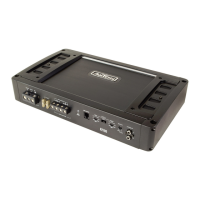
1. CONNECTIONS + CONTROLS A100 - PAGE I
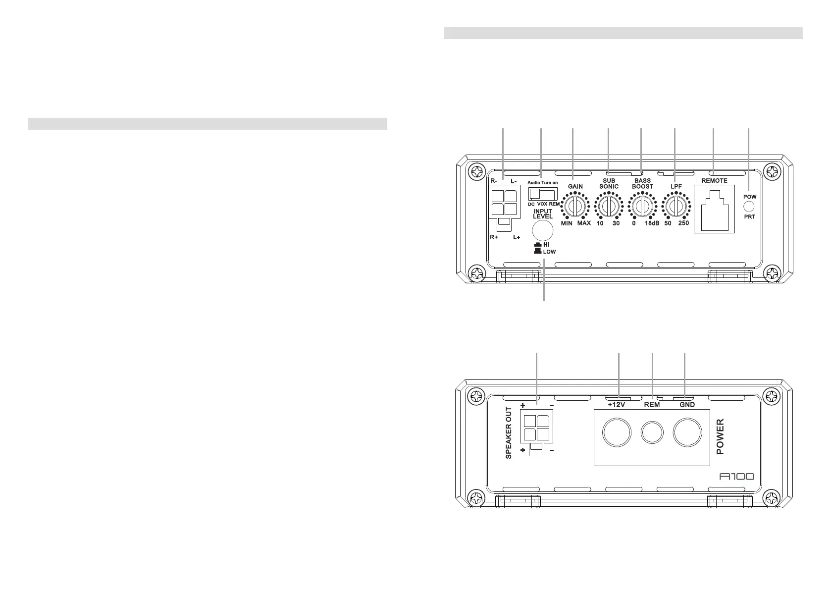
1 SIGNAL INPUTS R / L
Low-level stereo RCA signal or high-level speaker signal input terminal for connection to
head-unit.
2 AUTO-TURN-ON MODE
Slide switch to select the auto-turn-on function: REM by remote wire, VOX to switch on
bymusicsignalorDCbyDCoffsetsignaloftheheadunitsintegratedamplier.
3 INPUT GAIN CONTROL
Input gain potentiometer for the subwoofer output channel, to match the output voltage
oftheheadunittotheamplier’sinput.
4 SUBSONIC HIGHPASS FREQUENCY CONTROL
Controlpotentiometertoadjustthesubsonichighpasslteringfrequencypointofthe
subwoofer output channel.
5 BASS BOOST 0dB to + 18dB
Turn clockwise to get up to + 18dB bass boost or counterclockwise for no boost with a
45Hzcenterfrequencyoftheampliedoutputsignal.
6 LOWPASS FREQUENCY CONTROL
Controlpotentiometertoadjustthelowpasslteringfrequencypointofthesubwoofer
output channel.
7 BASS LEVEL REMOTE CONTROL INPUT 1/2-CH
Inputterminaltoconnecttheexternalbasslevelremotetotheamplier.
8 POWER LED
LEDtoshowtheoperatingstatusoftheamplierbyblue/redillumination.Blueis
normalworkingstate,redisprotectmodeofamplier.
9 INPUT MODE SELECTION
Switch to select the proper input sensitivity range: RCA signal input = Low. Speaker
signal input = Hi.
10 SPEAKER OUTPUT TERMINAL
Outputterminaltoconnectthespeakerstotheamplier.
11 “+12 V” POWER INPUT TERMINAL
Terminaltoconnecttheampliertothepositive+12Vpoleofthecarbattery.
12 “REM” INPUT TERMINAL
Terminaltoconnecttheampliertotheautomatic(remote)turn-on/turn-offleadofthe
head unit. By using the REM terminal, you need to switch the Auto-turn-On mode
2
to
the “REM” position.
1. CONNECTIONS + CONTROLS A100 - PAGE II
ThankyouforpurchasingthisAXTONamplier!
Tomaximizetheperformanceofthisamplierandyourcompletecaraudiosysteminstall,we
recommendthatyouacquaintyourselfthoroughlywithalltechnicalfeaturesandcontrolling
options of thisAXTON amplier. Please read this manual carefully, before attempting the
installation.
If,afterreadingthismanual,youstillhavequestionsregardingfunctionsortheinstallationof
theamplier,werecommendthatyouconsultyourdealer.
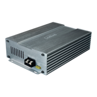
13 “GND” POWER INPUT TERMINAL
Terminaltoconnecttheampliertothechassisgroundornegativepoleofthecar
battery.
bl bm bn bo
40.0 mm
105.0 mm
173.5 mm
MODEL:CM350.1D
40.0 mm
105.0 mm
173.5 mm
MODEL:CM350.1D
1 2 3 4 5 6 7 8
9
 Loading...