Do you have a question about the AXTON C109 and is the answer not in the manual?
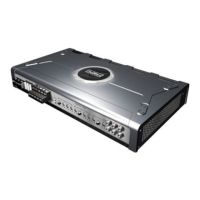
Lists the main technical features of AXTON C109/C209/C409/C509 amplifiers.
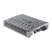
Low-level RCA signal input for connection to head-unit pre-out.
Input gain/sensitivity control for matching amplifier input to head-unit output.
Lowpass crossover filter frequency control (10-300 Hz).
Selects amplifier operation mode: Fullrange or Lowpass.
Subsonic crossover frequency control (10-60 Hz).
Protects amplifier internal electronics from overload/faults.
Power connection terminal to positive terminal of car battery.
Remote switching contact for automatic turn-on/turn-off.
Power connection terminal to chassis ground or negative battery terminal.
Speaker output terminals for subwoofers (min. 2 Ohms).
Amplifier status LED, green when power is on.
Amplifier status LED, red when in protect mode.
Input for external bass level remote control (RJ11 jack).
Low level RCA signal output for daisy-chaining.
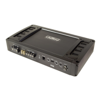
Low-level RCA signal input for connection to head-unit pre-out.
Input gain/sensitivity control for matching amplifier input to head-unit output.
Lowpass crossover filter frequency control (40-240 Hz).
Selects amplifier operation mode: Fullrange, Highpass, or Lowpass.
Highpass crossover filter frequency control (40-240 Hz).
Protects amplifier internal electronics from overload/faults.
Power connection terminal to positive terminal of car battery.
Remote switching contact for automatic turn-on/turn-off.
Power connection terminal to chassis ground or negative battery terminal.
Speaker output terminals for stereo or bridged mode (min. 4 Ohms).
Amplifier status LED, green when power is on.
Amplifier status LED, red when in protect mode.
Low-level RCA input for front speakers (Fullrange/Highpass).
Low-level RCA input for rear speakers or subwoofer (Fullrange/Lowpass).
Selects mode for channels 1+2: Fullrange or Lowpass.
Separate gain controls for channels 1+2 and 3+4.
Highpass filter frequency control for channels 1+2 (40-240 Hz).
Lowpass filter frequency control for channels 1+2 (50-200 Hz).
Lowpass filter frequency control for channels 3+4 (50-200 Hz).
Highpass filter frequency control for channels 3+4 (40-240 Hz).
Selects mode for channels 3+4: Fullrange or Highpass.
Amplifier status LED, green when power is on.
Amplifier status LED, red when in protect mode.
Protects amplifier internal electronics from overload/faults.
Power connection terminal to positive terminal of car battery.
Remote switching contact for automatic turn-on/turn-off.
Power connection terminal to chassis ground or negative battery terminal.
Speaker output terminals for channels 1+2.
Speaker output terminals for channels 3+4 (min. 4 Ohms bridged).
Proper mounting affects heat dissipation, cooling, and stability.
Mount on solid surface, avoid dust, direct sunlight, humidity, water, oil.
Use screws, avoid contact with metal parts to prevent ground loops.
Use double or triple shielded quality RCA cables for audio signals.
Route signal cables away from power/speaker/ignition wires.
Keep cables short; shielded RCA cables should not be cut.
Use recommended cross-section to avoid power loss, distortion, or overheating.
Install main fuse within 30 cm of car battery for +12V power input.
Use same cross-section as +12V cable; ensure good chassis ground contact.
Protect cables from shorting to chassis using rubber grommets.
Disconnect +12V terminal before wiring; connect last.
Disconnect the +12V main power cable from the car battery before any work.
Table of power cable cross-sections and main fuse values for amplifier models.
Step-by-step guide for connecting the amplifier, starting with head-unit off.
Connect head-unit RCA outputs to amplifier RCA inputs.
Use fullrange signals for sub pre-outs; avoid low-pass pre-outs.
Connect the remote lead from the head-unit to the amplifier.
Connect speaker cables to speakers, maintaining polarity. Notes on bridging.
Connect ground cable to chassis or -12V battery pole, ensuring short length and clean contact.
Connect +12V power to battery positive pole last, after checking all other connections.
C209/C409 can be used in Fullrange, Highpass, or Lowpass mode.
Stereo: 2-4 Ohms. Bridged mono: min. 4 Ohms.
For mono/bridged, both L&R inputs must be used (Y-adaptors if needed).
Main fuse (not included) must be within 30 cm of the car battery.
Minimum speaker impedance for all channels is 2 Ohms.
Main fuse (not included) must be within 30 cm of the car battery.
Minimum speaker impedance for all channels is 2 Ohms.
For mono/bridged, both L&R inputs must be used (Y-adaptors if needed).
Main fuse (not included) must be within 30 cm of the car battery.
C509 in any mode has a minimum impedance of 2 Ohms.
Main fuse (not included) must be within 30 cm of the car battery.
Guide for adjusting amplifier controls based on amplifier type and mode.
Explains Highpass (HPF) and Lowpass (LPF) modes for speakers and subwoofers.
Adjust system crossover frequencies using FILTER FREQ. controls.
Set head unit tone, fader, balance to neutral before adjustment.
The "Loudness" function should be deactivated during adjustments.
Setting HPF for satellites affects mid-bass and power handling.
Provides HPF frequency recommendations for different satellite speaker sizes.
Setting LPF for subwoofer affects bass precision and response.
Set tone, fader, balance controls to neutral; turn off "Loudness".
Turn GAIN controls to lowest position before starting adjustments.
Turn head-unit volume to approx. 3/4 full and play dynamic music.
Turn GAIN up until distortion, then decrease until distortion disappears.
Adjust GAIN for subwoofers until distorted bass, then decrease.
Fine-tune subwoofer (LPF) first, then front/rear satellites (HPF).
Checks for proper connections, blown fuses, short circuits, DC voltage, overload, or overheating.
Checks for bad ground contact or poor RCA cable shielding/routing.
Checks for ignition circuitry interference.
Checks for ground loop issues and other connected audio components.
Explains protection circuitry for short-circuit, overload, DC offset, or overheat.
Table details rated power output at different impedances and modes for each model.
Lists the frequency response range for all models.
Details Total Harmonic Distortion (THD) and Signal to Noise Ratio.
Specifies crossover slope, range, input impedance, and speaker impedance.
Lists fuse ratings and physical dimensions for each amplifier model.
Product is warranted against defects for 2 YEARS from date of purchase at retail.
Lists conditions not covered, such as improper use, exposure, or unauthorized repairs.