– 4 – – 5 –
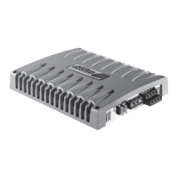
1. CONNECTIONS + CONTROLS A200 - PAGE I
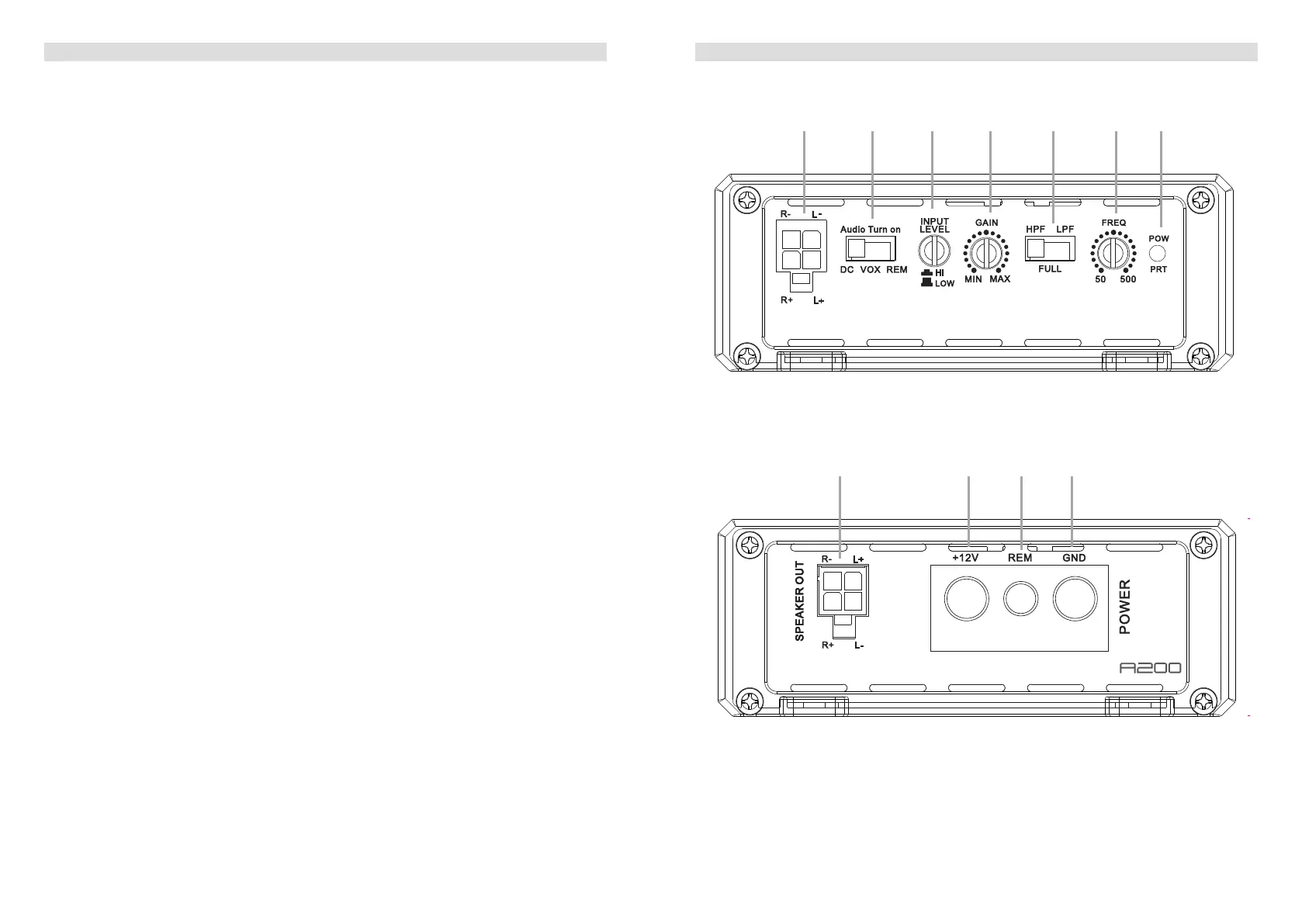
1 SIGNAL INPUTS R / L
Low-level stereo RCA signal or high-level speaker signal input terminal for connection
to head-unit.
2 AUTO-TURN-ON MODE
Slide switch to select the auto-turn-on function: REM by remote wire, VOX to switch on
bymusicsignalorDCbyDCoffsetsignaloftheheadunitsintegratedamplier.
3 INPUT MODE SELECTION
Switch to select the proper input sensitivity range: RCA signal input = Low. Speaker
signal input = Hi.
4 INPUT GAIN CONTROL
Input gain potentiometer for the subwoofer output channel, to match the output voltage
oftheheadunittotheamplier’sinput.
5 OPERATION MODE SWITCH
SlideswitchtoselecttheoperationmodeoftheX-overoftheamplier:Highpass
[HPF],Lowpass[LPF]orfullsignal
6 X-OVER FREQUENCY CONTROL
Controlpotentiometertoadjustthehighpassorlowpasslteringfrequencyofthe
amplier.
7 POWER LED
LEDtoshowtheoperatingstatusoftheamplierbyblue/redillumination.Blueis
normalworkingmode,redisprotectmodeofamplier.
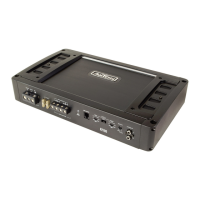
8 SPEAKER OUTPUT TERMINAL
Outputterminaltoconnectthespeakerstotheamplierineitherstereoorbridged
mode.
9 “+12 V” POWER INPUT TERMINAL
Terminaltoconnecttheampliertothepositive+12Vpoleofthecarbattery.
10 “REM” INPUT TERMINAL
Terminaltoconnecttheampliertotheautomatic(remote)turn-on/turn-offleadofthe
head unit. By using the REM terminal, you need to switch the Auto-turn-On mode
2
to the “REM” position.
11 “GND” POWER INPUT TERMINAL
Terminaltoconnecttheampliertothechassisgroundornegativepoleofthecar
battery.
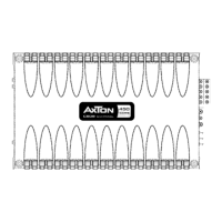
1. CONNECTIONS + CONTROLS A200 - PAGE II
183.6 mm
105.0 mm
40.0 mm
MODEL:CM150.2D
8 9 bl bm
183.6 mm
105.0 mm
40.0 mm
MODEL:CM150.2D
31 4 5 6 72