– 8 – – 9 –
1. CONNECTIONS + CONTROLS A500 - PAGE I
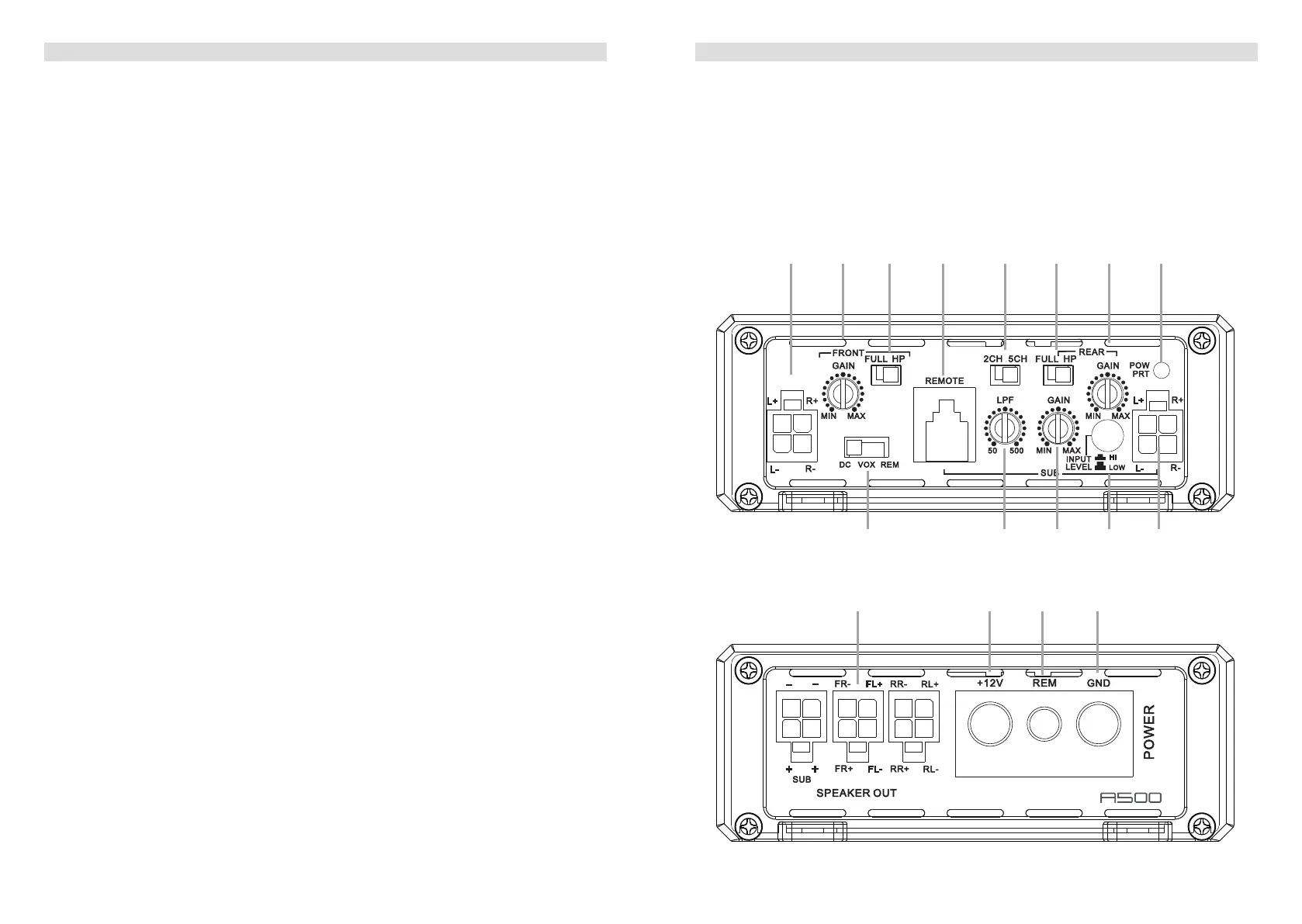
1 SIGNAL INPUTS FRONT R / L and REAR R / L
FrontandRearchannelLow-levelstereoRCAsignalorhigh-levelspeakersignalinput
terminals for connection to head-unit.
2 INPUT GAIN CONTROL FRONT CHANNELS
InputgainpotentiometerforchannelFL/FR-CH,tomatchtheoutputvoltageofthehead
unittotheamplier’sinput.
3 OPERATION MODE SWITCH FRONT CHANNELS
SlideswitchtoselecttheoperationmodeoftheX-overforsectionFL/FR-CHofthe
amplier:50HzHighpassorfullsignal.
4 BASS LEVEL REMOTE CONTROL INPUT
Inputterminaltoconnecttheexternalbasslevelremotetotheamplier.
5 INPUT SIGNAL SELECTION
Slide switch to select the input signal for all channels. “2-CH” to use only front input
terminal for all output channels. “5-CH” to give each output channel its corresponding
inputchannel(theCH5issummarizedbyall4inputchannels).
6 OPERATION MODE SWITCH REAR CHANNELS
SlideswitchtoselecttheoperationmodeoftheX-overforsectionRL/RR-CHofthe
amplier:50HzHighpassorfullsignal.
7 INPUT GAIN CONTROL REAR CHANNELS
InputgainpotentiometerforchannelRL/RR-CH,tomatchtheoutputvoltageofthehead
unittotheamplier’sinput.
8 POWER LED
LEDtoshowtheoperatingstatusoftheamplierbyblue/redillumination.Blueis
normalworkingstate,redisprotectmodeofamplier.
9 AUTO-TURN-ON MODE
Slide switch to select the auto-turn-on function: REM by remote wire, VOX to switch on
bymusicsignalorDCbyDCoffsetsignaloftheheadunitsintegratedamplier.
10 LOWPASS FREQUENCY CONTROL SUBWOOFER CHANNEL
Controlpotentiometertoadjustthelowpasslteringfrequencypointofthesubwoofer
output channel.
11 INPUT GAIN CONTROL SUBWOOFER CHANNEL
Input gain potentiometer for subwoofer channel, to match the output voltage of the head
unittotheamplier’sinput.
12 INPUT MODE SELECTION
Switch to select the proper input sensitivity range: RCA signal input = Low. Speaker
signal input = Hi.
13 SPEAKER OUTPUT TERMINAL
Outputterminaltoconnectthespeakerstotheamplierineitherstereoorbridged
mode.
1. CONNECTIONS + CONTROLS A500 - PAGE II
14 “+12 V” POWER INPUT TERMINAL
Terminaltoconnecttheampliertothepositive+12Vpoleofthecarbattery.
15 “REM” INPUT TERMINAL
Terminaltoconnecttheampliertotheautomatic(remote)turn-on/turn-offleadofthe
head unit. You must switch
9
to “REM” when using the remote wire input terminal.
16 “GND” POWER INPUT TERMINAL
Terminaltoconnecttheampliertothechassisgroundornegativepoleofthecar
battery.
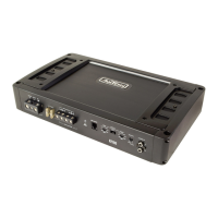
253.5 mm
105.0 mm
40.0 mm
MODEL:CM600.5D
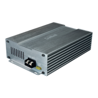
253.5 mm
105.0 mm
40.0 mm
MODEL:CM600.5D
2 3 4 5 6 7 81
9 bl bm bn 1
bo bp bq br
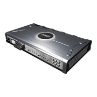
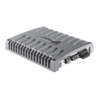
183.6 mm
105.0 mm
40.0 mm
MODEL:CM150.2D
S
PEA
KER
O
U
T
R-
L+
R
+
L-
BRIDGED
S
PEA
KER
OU
T
GND
+12V
REM
P
O
WER
Auto Turn On
 Loading...