– 6 – – 7 –
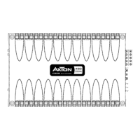
1. CONNECTIONS + CONTROLS A460
1.1 CONTROLS
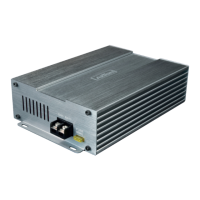
1 RCA INPUTS 1/2-CH
Low-level stereo RCA signal input 1/2-CH for connection to head-unit.
2 INPUT GAIN CONTROL 1/2-CH
Input gain potentiometer for channel 1/2-CH, to match the output voltage of the head-
unittotheamplier’sinput.
3 HIGH INPUT 1/2-CH
Molex connector terminal to insert the High level adapter (4-pin) that picks up the
ampliedspeakersignalfromtheheadunit’sfrontoutput(ifheadunitdoesnotfeature
dedicated RCA line outs).
4 OPERATION MODE SWITCH 1/2-CH
SlideswitchtoselecttheoperationmodeoftheX-overforsection1/2-CHoftheamplier.
5 X-OVER FREQUENCY CONTROL 1/2-CH
Controlpotentiometertoadjustthehighpassorlowpasslteringfrequencyforsection
1/2-CHoftheamplier.
6 RCA INPUTS 3/4-CH
Low-level stereo RCA signal input 3/4-CH for connection to head-unit.
7 INPUT GAIN CONTROL 3/4-CH
Input gain potentiometer for channel 3/4-CH, to match the output voltage of the head-
unittotheamplier’sinput.
8 HIGH INPUT 3/4-CH
Molex connector terminal to insert the High level adapter (4-pin) that picks up the
ampliedspeakersignalfromtheheadunit’srearoutput(ifheadunitdoesnotfeature
dedicated RCA line outs).
9 OPERATION MODE SWITCH 3/4-CH
SlideswitchtoselecttheoperationmodeoftheX-overforsection3/4-CHoftheamplier.
10 X-OVER FREQUENCY CONTROL 3/4-CH
Controlpotentiometertoadjustthehighpassorlowpasslteringfrequencyforsection
3/4-CHoftheamplier.
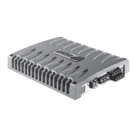
1.2 INPUTS + OUTPUTS
11 POWER LED
LEDtoshow“operating”statusoftheamplierbygreen/redillumination.Greenis
normalworkingstate,redisprotectstateofamplier.
12 “GND” POWER INPUT TERMINAL
Terminaltoconnecttheampliertothechassisgroundornegativepoleofthecarbattery.
13 “REM” INPUT TERMINAL
Terminaltoconnecttheampliertotheautomatic(remote)turn-on/turn-offleadofthe
head unit.
1. CONNECTIONS + CONTROLS A460
14 “+12 V” POWER INPUT TERMINAL
Terminaltoconnecttheampliertothepositive+12Vpoleofthecarbattery.
15 SPEAKER OUTPUT TERMINAL
Outputterminaltoconnectthespeakerstotheamplierineitherstereoorbridged
mode.
2 3 4 5
bo bp bqbm bn
6
7 8 9
bl
1