LPF FILTER
Crossover filter frequency control allowing the setting of the
Lowpass cut-off frequency between 50 and 250 Hz.
Note: This control is not active when the amplification mode
switch is in ''Fullrange'' position!
AMPLIFICATION MODE SWITCH
Depending on the selected switch setting the amplifier ope-
rates in Highpass, Lowpass or Fullrange mode.
HPF FILTER
Crossover filter frequency control allowing the setting of the
High-pass cut-in frequency between 50 and 250 Hz.
Note: This control is not active when the amplification mode
switch is in ''Fullrange'' position!
INPUT GAIN
Input gain/sensitivity control allowing the matching of the
amplifier input section to the head-unit (pre-out)
output voltage.
INPUT CH1-CH4
Low-level RCA input for connection to head-unit pre-out.
NOTE:
Upper row for CH1 and CH2. Lower row for CH3 and CH4.
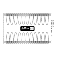
q GROUND/GND
Power connection terminal to chassis ground or negative
terminal of car battery.
w REMOTE/REM
Remote switching contact for the remote on/off toggling of
the power amplifier from the head-unit's remote lead.
e +12 V
Power connection terminal to positive terminal of car battery.
r FUSE
Fuses for protection of the amplifier-internal electronics
against overload or faulty operation / wrong manipulation.
t +CH1– through – CH4+
Speaker output terminals for one stereo speaker pair or one
single speaker connected in bridged mode (e.g. subwoofer).
In bridged mode the minimum speaker impedance is 4 ohms!
y POWER LED/PROTECT LED
Lit green when power is on. Lit red when amplifier is in pro-
tect mode due to shorted speakers, overtemp. etc.
u REMOTE PORT
Input for RJ11 jack, for the external bass level
remote control.
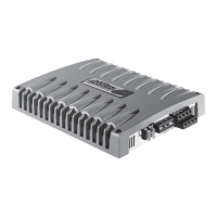
B3
CONNECTIONS AND CONTROLS AXTON A490