– 6 – – 7 –
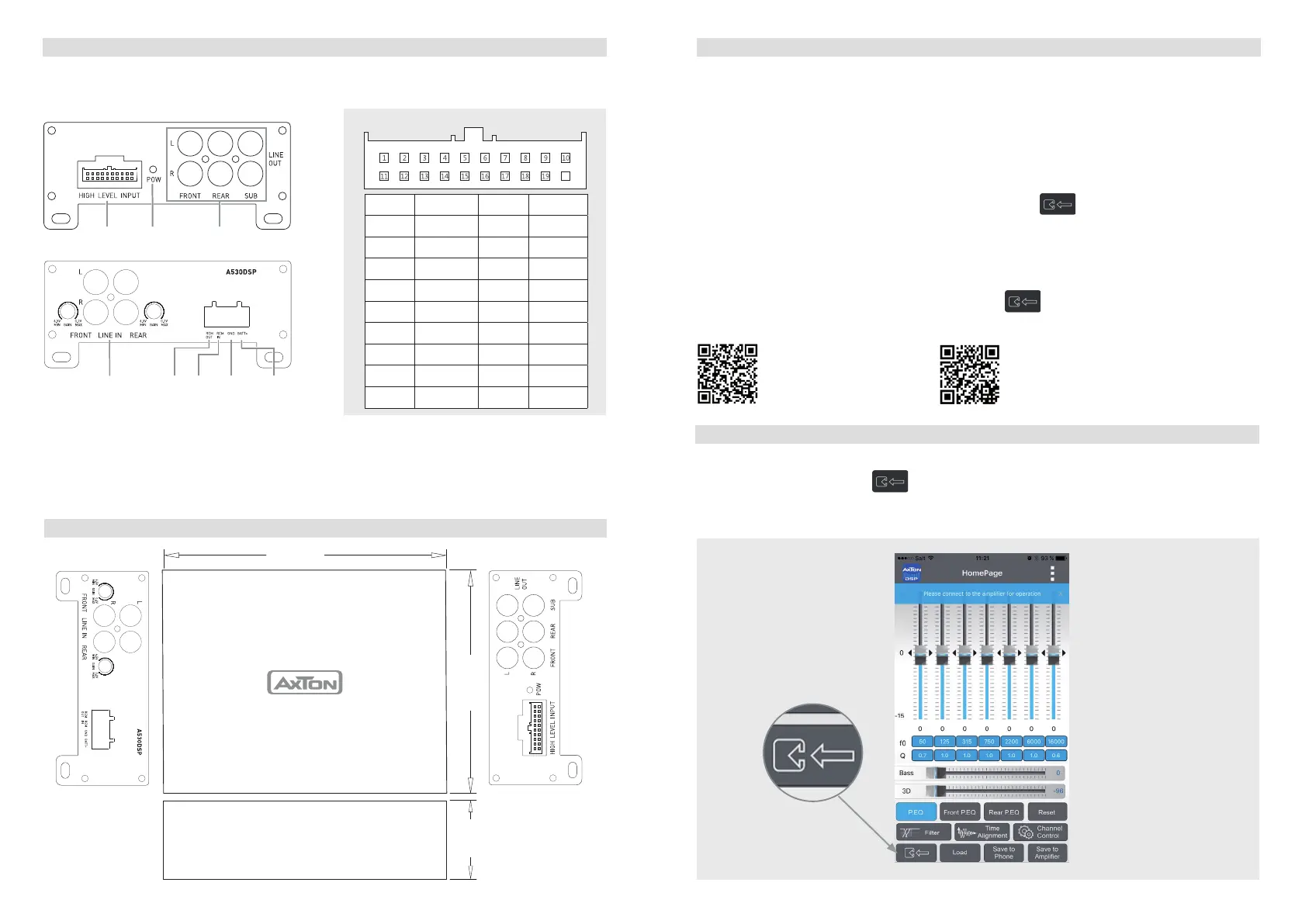
WIRING DIAGRAM
DIMENSIONS
If you want to use just the DSP function of the A530DSP with a separate high performance
amplifier, connect the line out of the A530DSP with the RCA input of your amplifier.
APP INSTALLATION
For Android phones only:
1. Download the A530DSP_V1.0.apk by scan of the QR code or download from the Axton
website www.axton.de
2. Install A530DSP_V1.0.apk to your Android smart phone.
3. Turn on Bluetooth on your mobile and search “A530DSP”, then connect to it with paring
code 1234.
4. Open A530DSP app and click the “Connect” button
to connect your mobile to the
amplifier.
For iOS smart phones only:
1 Visit the Apple AppStore, search for „A530DSP“ and install the app.
2 Turn on Bluetooth.
3. Open the app and press the “Connect” button
in order to connect the amp with
the app.
A530DSP FUNCTIONS
Connecting to the smart mobile
Touch the “Connect” button
to connect the mobile to the ampli er. After the
connecting procedure is done successfully, you are automatically in the EQ menu and the
app loads the settings from the ampli er.
Scan to download and
install the app from the
Apple AppStore
UI: Connecting
Touch to
connect to
the amp.
1* In some cases with old headunits the Auto-Turn-On function cannot work. If you meet this problem, please
just put the separately provided wire “ACC-IN” into the connector of the connection cable and connect it to
ACC/Amp Remote of the car stereo or another cable which will provide +12 V only when the car stereo is
turned on.
2* REM-Out: Connect this wire to the remote input of a separate amplifier, for example a mono amp for a
subwoofer.
Scan to download and
install the app from the
Axton homepage
BATT+LINE IN
FRONT / REAR
REM
OUT
REM
IN
GND
HIGH LEVEL
INPUT
Model No.: MDA-100
FR+in
FR-in
FL+in
FL-in
RL+in
RL-in
RR+in
RR-in
RR-out
RR+out
RL-out
RL+out
FR-out
FR+out
FL-out
FL+out
+B
GND
20
Wire Diagram
USER MANUAL
Installation Diagram
POWER LINE OUT
20
1* ACC-in 11 GND
2*
Rem-out
12
+B
3
RR-in
13
4
RR+in
14
5
RL-in
15
6
RL+in
16
7
FL-in
17
8
FL+in
18
9
FR-in
19
10
FR+in
20
PLUG AND PLAY HIGH LEVEL INPUT
151 mm
114 mm
40 mm
Model No.: MDA-100
FR+in
FR-in
FL+in
FL-in
RL+in
RL-in
RR+in
RR-in
RR-out
RR+out
RL-out
RL+out
FR-out
FR+out
FL-out
FL+out
+B
GND
20
Wire Diagram
USER MANUAL
Installation Diagram
 Loading...