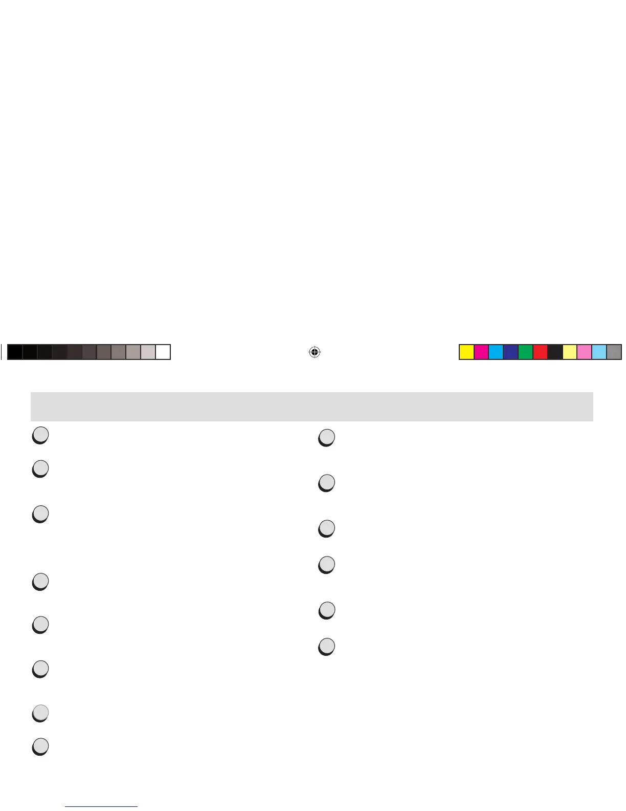
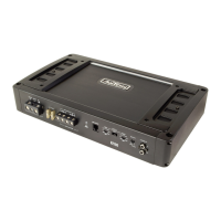
26
9
G R O U N D / G N D
Power connection terminal to chassis ground or negative
terminal of car battery (-12 V)
10
L und R
Speaker output terminals for one or two subwoofers.
The minium speaker impedance is 2 Ohms!
11
P O W E R L E D
Amplifier status-LED. Lit green when power is on.
12
PROTECT LED
Lit red when amplifier is in protect mode due to shorted speakers,
overtemperature etc.
13
R E M O T E P O R T
Input for RJ11 jack, for the external bass level remote control.
14
OUTPUT L + R
Low level RCA signal output, to daisy-chain the RCA input signal to
another amplifier.
1
INPUT L+R
Low-level RCA signal input for connection to head-unit pre-out.
2
INPUT GAIN
Input gain/sensitivity control allowing the matching of the amplifier
input section to the head-unit (pre-out) output voltage.
3
FILTER FREQ. LPF
Crossover filter frequency control allowing the setting of the Lowpass
cut-off frequency between 10 and 300 Hz.
Note: This control is not active when the amplification mode switch is
in the ''Fullrange'' position!
4
AMPLIFICATION MODE SWITCH
Depending on the selected switch setting the amplifier operates in
Fullrange or Lowpass mode.
5
FILTER FREQ. SUBSONIC
Crossover frequency control allowing the setting of the Subsonic cut-
in frequency between 10 and 60 Hz.
6
FUSE
Fuses for protection of the amplifier-internal electronics against over-
load or faulty operation / wrong manipulation.
7
+ 12 V
Power connection terminal to positive terminal of car battery.
8
REMOTE/REM
Remote switiching contact for the automatic (remote) turn-on / turn-
off of the power amplifier from the head-unit's remote (or antenna
control) lead.
B1
CONNECTIONS AND CONTROLS AXTON C109