EasyManua.ls Logo

Axxess GMRC-04 User Manual

Axxess GMRC-04
3 pages
To Next Page IconTo Next Page
Page #1 background imageLoading...
Page #1 background image
Installation instructions for part GMRC-04
Axxess Integrate
CAUTION!
All accessories, switches, climate controls panels, and
especially air bag indicator lights must be connected before cycling
the ignition. Also, do not remove the factory radio with the key in the
on position, or while the vehicle is running.
Provides accessory (12-volt 10-amp)
Retains R.A.P. (Retained Accessory Power), if equipped
Used in non-amplified systems or when replacing amplified systems
Retains all warning chimes through onboard speaker
FEATURES
GMRC-04
GM Class II data bus interface
2000-2005
GMRC-04 data interface
10-pin to 32-pin GM harness
INTERFACE COMPONENTS
APPLICATIONS
BUICK
Le Sabre 2000-2005
OLDSMOBILE
Aurora 2001-2003
PONTIAC
Bonneville 2000-2005
Connections to be made ................................................... 2
Installing the GMRC-04 .................................................... 3
TABLE OF CONTENTS
• Cutting tool • Crimping tool • Tape
• Connectors (example: butt-connectors, bell caps, etc.)
TOOLS REQUIRED
Question and Answer IconNeed help?

Do you have a question about the Axxess GMRC-04 and is the answer not in the manual?

Axxess GMRC-04 Specifications

General IconGeneral
BrandAxxess
ModelGMRC-04
CategoryRecording Equipment
LanguageEnglish

Summary

Features and Components

Features

Lists key functionalities of the GMRC-04 interface, including 12-volt accessory power, R.A.P. retention, and chime retention.

Interface Components

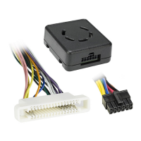
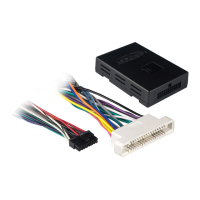
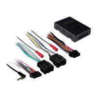
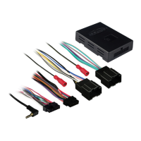
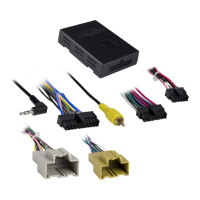
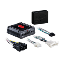
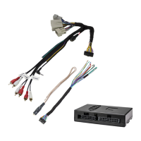
Identifies the physical parts included with the GMRC-04, such as the data interface module and the GM harness.

Applications

Specifies compatible vehicle makes and models, including Buick Le Sabre, Oldsmobile Aurora, and Pontiac Bonneville.

Tools Required

Lists necessary tools for installation, such as cutting tools, crimping tools, tape, and connectors.

Connections to be Made

10-Pin Harness Connections

Details connecting the red wire from the 10-pin harness to the radio's 12-volt accessory or switched wire.

32-Pin Harness Connections

Outlines connections for yellow (constant), black (ground), blue (antenna/amp turn-on), orange (illumination), and speaker wires.

Installing the GMRC-04

Post-Connection Steps

Instructions to plug the 32-pin harness into the vehicle and cycle ignition to test the radio functionality.

Mounting Location

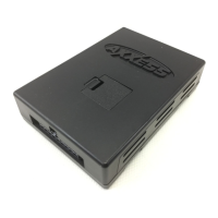
Guidance on mounting the GMRC-04 where its internal speaker output is audible.

Chime Volume Adjustment

Note on reducing chime volume by cutting a specific solder connection on the circuit board.

Related product manuals