10
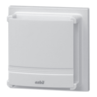
AB-7521
•
Corrosive gas, organic solvent, or other
chemicals is contained in the atmosphere.
•
Chemicals or oils adhere.
When they adhered, wipe them immediately with
a dry soft cloth.
If chemicals or oils remain on the case, chemical
cracks may be made on it.
•
Do not install the sensor outdoors or in a duct.
•
Do not horizontally install the sensor directly on
a ceiling surface.
z
Notes for installation
IMPORTANT
•
Do not touch the temperature and humidity
sensing elements on the PCB assembly
(Fig. 8) when removing/attaching the
cover and when installing the main unit.
Measuring accuracy may drop.
element
Humidity sensing
element
Note: The temperature/humidity sensor is illustrated as an
example.
For the humidity sensor, only the humidity sensing ele-
ment is aected.
Figure 8. Temperature/humidity sensing elements
•
Use the dedicated mounting kit (optional parts)
suitable for your application.
•
Do not allow any refuse such as an electric wire
scrap to get inside the sensor.
•
Do not get a cable caught between the sensor
and the mounting surface.
•
When attaching the cover, carefully handle the
sensor not to damage the temperature/humidity
sensing elements.
•
Be aware that if the sensor is horizontally
installed not only on the ceiling surface, sucient
ambient air velocity may not be obtained.
•
If air inltrates to the rear side of the sensor from
the inside of the installed wall through the outlet
box, shut o the air by sealing the outlet box.
•
After installation, leave the sensor well so that
it adapts to ambient conditions (atmospheric
environment) .
z
Installation procedure
There are several methods for installing the sensor,
Wall-direct mounting, Thermoplate for open wiring
mounting,Thermoplate mounting, and Multi-
thermocase mounting.
Wall-direct mounting
(1) Attach the mounting plate of Wall-direct
mounting kit to the outlet box cover (JIS
C8340:1999, mounting dimension for outlet box
66.7 mm) on the mounting surface.
Use the 2 screws (M4, pan-head, L = 8)
supplied with the sensor.
Mounting box cover
JIS C8340, mounting
dimension 66.7 mm
66.7mm
Wires from the load
Mounting plate
2 pan-head screws
(M4, L = 8)
66.7mm
(2) Attach the main unit of the Wall-direct mounting
kit to the mounting plate.
Use the 1 screw (M3, flat-head, L = 16)
supplied with the sensor.
Mounting plate
Main unit of
Wall-direct
mounting kit
1 flat-head screw
(M3, L = 16)
Mounting plate
Main unit of
Wall-direct
mounting kit
Rear
surface
(3) Connect the lead wires of the main unit and the
wires from the load.
Refer to Figs. 17 and 18 in ■ “Wiring.”
(4) Detach the cover of the main unit.
Push the spring, located inside the top of the
main unit, using a thin rod to remove the cover.
mounting kit

 Loading...