AB-6546
15
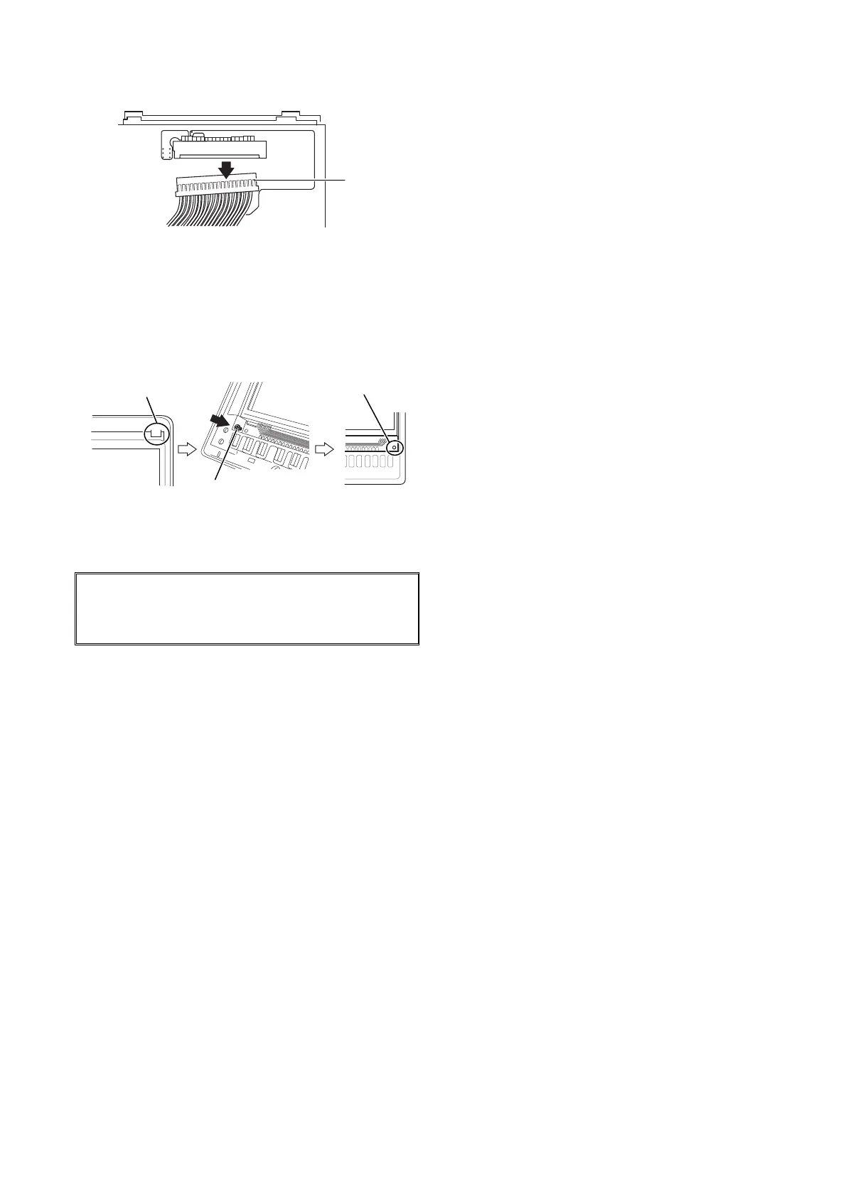
5) Disconnect the connector to remove the LCD module.
Figure 15. Connector disconnection
6) Mount a new LCD module.
Connect the connector and hook the LCD module with
the claws of the LCD board.
Insert the screw into the hole located at the lower left of
the LCD board, and then engage the LCD module with
the boss at the lower right of the LCD board.
Figure 16. LCD module mounting
7) When the LCD module fits to the LCD board, tighten the
screw at the lower left of the LCD board (in one location).
IMPORTANT:
Screw-tightening torque is 0.07 N⋅m (0.7 kgf⋅cm).
Larger torque than 0.07 N⋅m may break the screw.
8) Attach the transparent cover to the LCD module. (The
wider side surface (to be inserted into the LCD module)
needs to be located on the right.)
9) Mount the front panel.
Model RY5001Q0000 (integral type)
Any part replacement is not available for Model
RY5001Q0000. If any part of Model RY5001Q0000 gets
damaged, the whole unit requires to be replaced.
For details regarding the maintenance, ask Azbil
Corporation’s sales personnel.
Connector
Claw
Screw
Boss
 Loading...