Thank you for purchasing the RN748.
Before operating the product described in this user’s manual, please
take note of the following points regarding safety.
Be sure to keep this manual nearby for handy reference.
This manual explains the handling precautions, mounting, wiring, list of
parameters and main specifications only.
■ Unpacking
Check the following items when removing the RN748 from its package:
The RN748 calculates the MV (OUT) for the input (IN) according to the
selection of direct/reverse control action, center setting of the rotation
angle, and the setting of the proportional band; it also controls the
ON/OFF status of the control output on the OPEN side and the CLOSE
side so that the motor opening (MFB) calculated from the motor
feedback input gets closer to the MV (OUT).
The figure below shows the functional blocks of the RN748.
■ Location
Install the RN748 in a location that fulfills the conditions listed below.
· For common mode voltages of I/O except for power supply and relay
contact output, the voltage to ground is 33Vr.m.s max., 46.7V peak max.,
and 70Vdc max.
· Neither high nor low temperature / humidity.
· Free from sulfide gas or corrosive gas.
· Little dust or soot.
· Locations protected from direct sunlight, wind or rain.
· Little mechanical vibration and shock.
· Not close to high voltage line, welding machine or electrical noise
generating source.
·A minimum of 15 meters away from a high voltage ignition device for a
boiler.
· No strong magnetic fields.
· No flammable liquid or gas.
■ Mounting Procedure
· Mounting should be horizontal so that the top is not tilted up or down
more than 10 degrees.
· The mounting panel should be steel with a thickness of less than 9 mm.
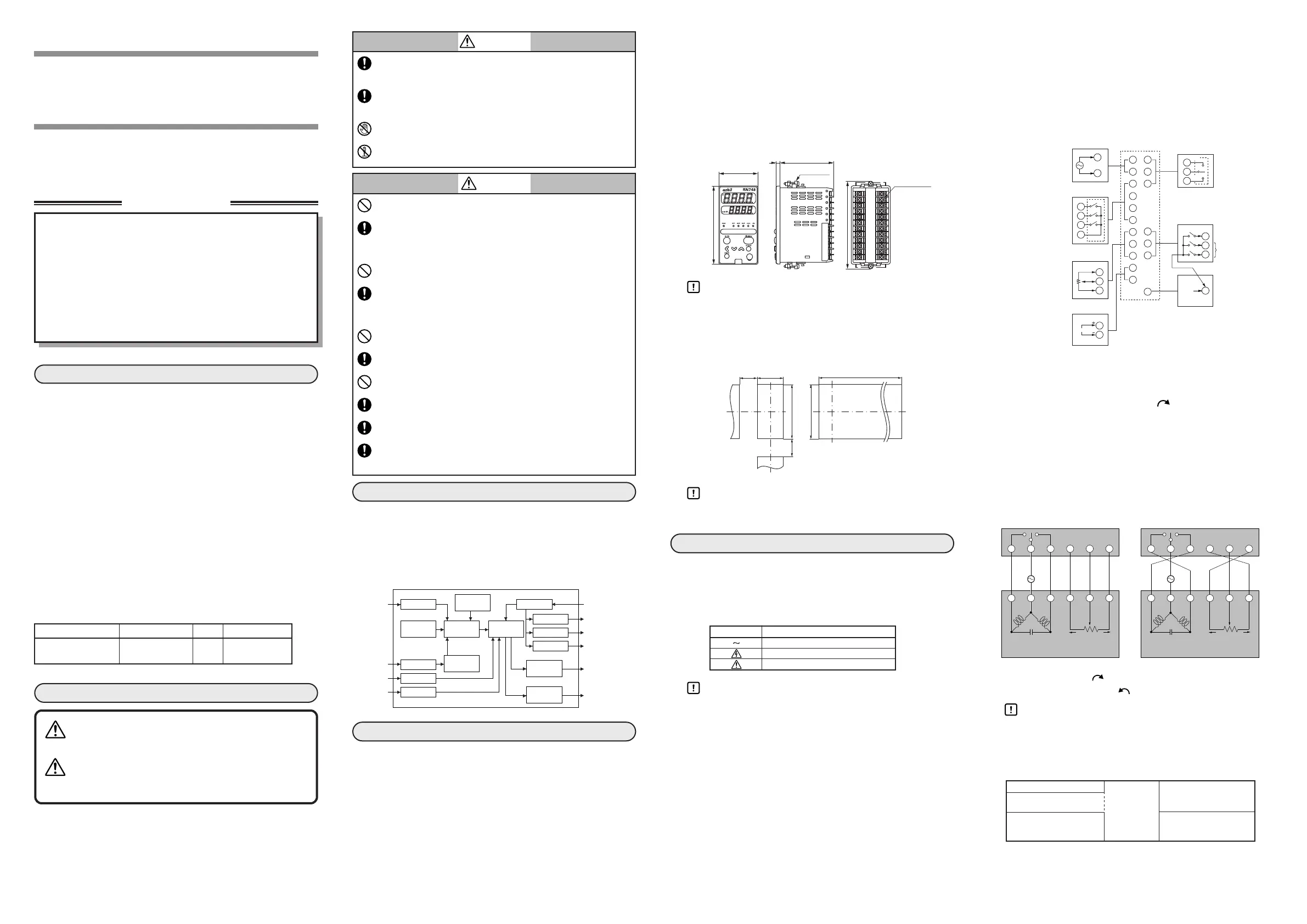
■ External Dimensions
Handling Precautions
• To fasten the RN748 onto the panel, tighten the mounting
bracket screws, and turn one more turn when there is no play
between the bracket and panel. Excessively tightening the
screws may deform the RN748 case.
■
Panel Cutout Dimensions
Handling Precautions
• When three or more units are gang-mounted horizontally, the
maximum allowable ambient temperature is 40°C.
Be sure to provide a switch within operator reach for shutting OFF the main
power supply to the RN748 in the main supply wiring.
Also, the main supply wiring requires a time-lagged (T) fuse (rated at 0.5A, 250
V). (IEC127)
The following table shows the meaning of the symbols in the terminal wiring
label on the side of the RN748:
Handling Precautions
• Before wiring the RN748, verify its model No. and terminal
Nos. written on the label on the side of the body. Inspect all
wiring after wiring work for the RN748 has been completed.
• Use M3 crimp-type terminal lugs for wiring to the terminals.
• Leave at least 50cm between I/O lead wires and power lead
wires. Also, do not pass these lead wires through the same
piping or wiring duct.
• When the power supply voltage of the motor that is connected
to the motor drive relay output is 100/200Vac, use an auxiliary
relay externally.
• Do not wire in the same duct for the motor drive terminals
(13),(14),(15) and the MFB input terminals (7),(8), (9), and also
do not use 6-core cable. Doing so might cause the RN748
malfunction due to noise during motor startup operation.
• Devices or equipment connected to the RN748 must have
basic insulation appropriate for the power supply voltage and
the maximum operating voltage of the I/O units.
• The RN748 requires a maximum of 5 seconds to start up after
the power is turned ON. The RN748 can be used after it has
started up. However, it is recommended to allow a warm-up
time of at least 30 minutes so that it attains the specified
accuracy.
● Connection of the RN748
● Direct wiring and reverse wiring
For wiring between the motor and the RN748, two wiring methods, direct
wiring and reverse wiring, are provided as described below. With direct
wiring the motor rotates clockwise (CW, ) as the output of the
RN748 increases.
If the control task requires the motor to rotate counterclockwise, as for
cooling control, two methods are provided as described below.
•The wiring is the same as for clockwise rotation, but the control
action direction is changed on the controller.
•Reverse wiring is used.
The control action (direct/reverse) can be changed on this unit. If direct
wiring is used for the wiring to the motor, the control action is simple to
understand and trouble can be solved easily. Therefore, direct wiring is
recommended where possible.
CW: clockwise,
CCW: counterclockwise,
Handling Precautions
• Terminal numbers of the motor are sample numbers from the
ECM3000. If you use a motor other than the ECM3000, make
connections following the manual for the motor.
● I/O isolation
Items surrounded by solid lines are insulated from other signals.
CP-UM-5376JE
RN748
Motor Driver (DC to Position
Proportional Control Converter)
User's Manual
Do not operate the keys with a mechanical pencil or sharp-tipped
object. Doing so might cause faulty operation.
Use the RN748 within the operating ranges recommended in the
specifications (for temperature, humidity, voltage, vibration, shock,
mounting direction, atmosphere, etc.). Failure to do so might
cause fire or faulty operation.
Do not block ventilation holes. Doing so might cause fire or faulty
operation.
Wire the RN748 properly according to predetermined standards.
Also wire the RN748 using specified power leads according to
recognized installation methods. Failure to do so might cause
electric shock, fire or faulty operation.
Do not allow lead clippings, chips or water to enter the controller case.
Doing so might cause fire or faulty operation.
Firmly tighten the terminal screws at the torque listed in the specifications.
Insufficient tightening of terminal screws might cause electric shock or fire.
Do not use unused terminals on the RN748 as relay terminals.
Doing so might cause electric shock, fire or faulty operation.
We recommend attaching the terminal cover (sold separately) after
wiring the RN748. Failure to do so might cause electric shock.
Use the relays within the recommended service life. Failure to do
so might cause fire or faulty operation.
Use Yamatake Corporation's "SurgeNon" if there is a risk of
power surges caused by lightning. Failure to do so might cause
fire or faulty operation.
CAUTION
30min.
30min.
This product has been designed, developed and manufactured for
general-purpose application in machinery and equipment.
Accordingly, when used in applications outlined below, special care
should be taken to implement a fail-safe and/or redundant design
concept as well as a periodic maintenance program.
• Safety devices for plant worker protection
• Start/stop control devices for transportation and material
handling machines
• Aeronautical/aerospace machines
• Control devices for nuclear reactors
Never use this product in applications where human safety may be
put at risk.
RESTRICTIONS ON USE
WARNING
Warnings are indicated when
mishandling this product might result in
death or serious injury to the user.
CAUTION
Cautions are indicated when mishandling
this product might result in minor injury to
the user, or only physical damage to this
product.
Note that incorrect wiring of the RN748 can damage it and lead to
other hazards. Check that the RN748 has been correctly wired
before turning the power ON.
Before wiring or removing/mounting the RN748, be sure to turn
the power OFF. Failure to do so might cause electric shock or
faulty operatoin.
Do not touch electrically charged parts such as the power terminals.
Doing so might cause electric shock.
Do not disassemble the RN748. Doing so might cause electric
shock or faulty operation.
WARNING
 Loading...