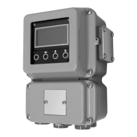
(1) Upper display: Displays input values (IN) or settings.
(2) Lower display: Displays manipulated variable (OUT), motor opening (MFB)
and other parameter values. When the display shows the
manipulated variable (OUT), the “out” lamp lights up.
(3) Mode indicator: man: Lights when in manual mode.
ev1 to ev3: Lights when event relays are ON.
opn • cls: Lights when the control output is ON.
(4) Multi-status
indicator: Through the combination of lighting conditions and lighting
status, 3 priority groups can be displayed.
(5) [a/m] key: Switches between AUTO and MANUAL mode when pushed
for 1s or more.
(6) [display] key: Used to change the display contents in the operation display
mode. Returns display from bank setup display to operation
display.
(7) <, , , key: Used for incrementing/decrementing numeric values and
performing arithmetic shift operations.
(8) [para] key: Switches the display.
(9) [enter] key: Used to set the setup values at the start of change and during
the change.
(10) Loader connector: Not available.
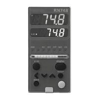
The following shows the key operation flow:
Handling Precautions
• When the [para] key is held down for 2 seconds or longer,
"LoC" will appear. This means you are at the lock setup
menu. Since there is no item to set up, press the [display] or
[a/m] key to return to the operation display.
● Setting example for position proportional control dead zone
Display "C58" on the upper display in the setup display mode. When the
[enter] key is pressed, the numerical value on the lower display will start to
flash. Move the digit and increase/decrese the numeric value by pressing
the [<][ ][ ] keys. When the [enter] key is pressed at the desired numeric
value, the flashing will stop and the data will be set.
● Setting example for motor auto adjustment
Display "C60" on the upper display in the setup display mode. When the
[enter] key is pressed, the numerical value on the lower display will start to
flash. Move the digit and increase/decrese the numeric value by pressing
the [<][ ][ ] keys. Set the value to "1" and press the [enter] key, and auto
adjust will start. The following items must be set up only when they are
changed from their defaults: center setting of the rotation angle,
proportional band setting, motor opening high/low limit event setting.
■ Selection of direct/reverse control action
You can select reverse or direct action of the RN748 by turning dital input 3
ON or OFF (DI3: between terminals 19 and 24) .
For the difference between direct and reverse action, see the figure in
"Setting example for the center of rotation and proportional band" (on
this page). Furthermore, you can switch between direct and reverse action
while running the RN748.
■ Adjustment and setting
Connect the RN748, controller, motor and other related devices correctly.
Then turn the power on and make adjustments and settings in the following
sequence:
(1) Do motor auto adjustment → (2) set the center of rotation angle → (3)
set the proportional band → (4) set the dead zone → (5) set the high/low
limit events for the motor opening.
The sections below show the details of each procedure.
■ Motor auto adjustment
Handling Precautions
• Be sure to execute auto adjustment. If the device is used
without doing auto adjustment, the motor may not operate
properly.
• Motor auto adjustment procedures
1. Set [C60: Motor auto adjustment] to 1 and press the [enter] key. If the C60
is already set to 1, press the [enter] key twice to perform this entry.
2. Motor auto adjustment then begins.
• The upper display shows and the relay on the CLOSE side is
turned ON.
• The motor rotates in the close direction, and the MFB count value is
written into [Fully closed adjustment value].
• The upper display shows , and the relay on the OPEN side is
turned ON.
• The motor rotates in the open direction, and the MFB count value is
shown on the lower display. When the counting stops, the fully open
adjustment is completed. This count value is then written into [Fully
open adjustment value]. Additionally, the period of time that has elapsed
from the fully closed position to the fully open position is written into
[Full opening time]. However, if this time is 240.0s or longer, this
parameter is set to 240.0s.
• When the motor auto adjustment has been completed, the basic display
screen will appear.
3. To cancel the adjustment, press the [display] key.
When motor auto adjustment starts, keys other than the [display] key,
which is used to cancel the adjustment, cannot be operated. If any of the
items below occurs, each value is returned to its default setting before
shipment and AL10 is shown as the troubleshooting process. AL10 is
cleared only when motor auto adjustment has been completed correctly or
when the power is reset.
• The count value between the fully closed position and fully open position
is less than 260.
• The fully closed count is greater than the fully open count.
• The period of time from the fully closed position to the fully open
position is less than 5s.
• The MFB burnout alarm (AL07) continues or occurs frequently.
• The time needed for the MFB count to stop exceeds 5min.
• The MFB or open/close relay has faulty wiring.
(However, not all faulty wiring can be detected as an error.)
Handling Precautions
• If the power to the RN748 is turned OFF during motor auto
adjustment of the position proportional control, motor auto
adjustment is cancelled when the power is turned ON again.
• Even if an AUTO/MANUAL mode changeover is made during
motor auto adjustment of the position proportional control, the
auto adjustment continues.
• If the control output (on the OPEN or CLOSE side) is forcibly
turned ON or OFF by the digital input 1 or 2 during auto
adjustment of the position proportional control, the auto
adjustment may continue. Even if it does not stop, the result
of adjustment is incorrect. It is necessary to repeat the
adjustment without forced ON/OFF.
• It is not possible to display the values saved for fully closed
adjustment value, fully open adjustment value, and full
opening time.
■ Motor auto adjustment operation
This unit has functions (AL07, AL10) that detect incorrect wiring to the
motor and MFB burnout or short-circuit. In the same manner as described
for direct wiring, the unit judges the reverse wiring as correct and does not
give any alarm. In addition, even if MFB burnout occurs, the operation
continues.
The tables below summarize characteristics of each wiring method when
motor auto adjustment is made (when [C60: Motor auto adjustment] is set to
[1: Start]). At this time, note that the motor is started from the fully closed
position (rotated fully counterclockwise). Numeric values shown in the
Lower display column of the tables are examples.
● Correct direct wiring
● Correct reverse wiring
● Alarm indications and causes due to incorrect wiring
■ Setting the center of rotation angle
When the center of the rotation angle is identical to the input (IN), the MV
(OUT) is 50%.
For details refer to:
Setting example "for the center of ratation and proportional band"
■ Setting the proportional band
When the input (IN) has changed by the amount of the proportional band
setting, the MV (OUT) changes in a range between 0 and 100%.
For details refer to:
Setting example "for the center of ratation and proportional band" below.
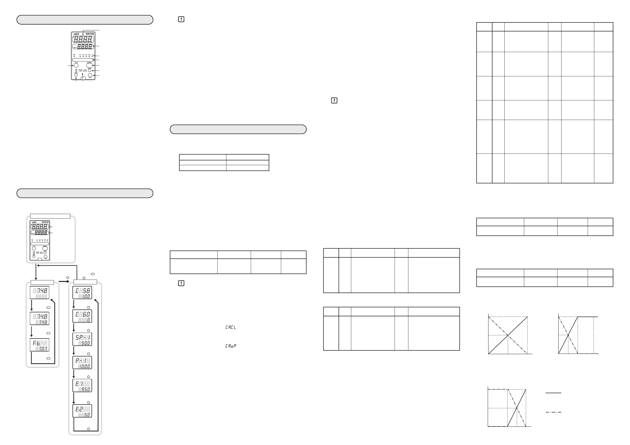
■ Setting example for the center of rotation and proportional band
1.
Center of rotation angle
: 50% (12mA) 2.
Center of rotation angle
: 25% (8mA)
Proportional band
: 100% (16mA)
Proportional band
: 50% (8mA)
3.
Center of rotation angle
: 75% (16mA)
Proportional band
: 50% (8mA)
<
<
<
<
<
<
or more.
Display when the power is turned ON.
E2
Operation preparation
Digital input 3 (DI3) Control action
OFF Direct action
ON Reverse action
Item Indication Contents Initial value
Motor auto adjustment
c60
0 : Stop 0
1 : Start
Upper display
Lit LED
Lower display
Motor motion
Remarks
CA.CL cls Shows a decrease CCW When the motor moves
like 2000 → 1500 and CCW with "cls" lit, motor
becomes stable. terminals 1 and 2 have
CA.OP opn Shows an increase CW direct wiring.
like 1500→3500 and
becomes stable.
Upper display
Lit LED
Lower display
Motor motion
Alarm indication Cause
CA.CL cls Increases and then CCW AL 10 G and Y
stops. are
CA.OP opn Decreases and then CW
connected
stops.
reversely.
CA.CL cls Increases and then CCW None. T and G
stops. However, the are
CA.OP opn Decreases and then CW MFB value does
connected
stops. not match the
reversely.
motor opening.
CA.CL cls Decrease or increase CCW AL 10 or none. T and Y
in unclear. are
CA.OP opn (Motor motion is CW
connected
changed before fully
reversely.
closed or opened.
CA.CL cls Increases and then CW AL 10 1 and 2
stops. are
CA.OP opn Decreases and then CCW
connected
stops.
reversely.
CA.CL cls Increases and then CW AL 10 1 and 2
stops.
connected
CA.OP opn Decreases and then CCW
reversely;
stops. T and G
are
connected
reversely.
CA.CL cls Decrease or increase CW AL 10 or none. 1 and 2
is unclear.
connected
CA.OP opn (Motor motion is CCW
reversely;
changed before fully T and G
closed or opened.)
connected
reversely.
↑
Upper display
Lit LED
Lower display
Motor motion
Remarks
CA.CL cls Shows a decrease like CW When the motor moves
3500 → 1500 and CW with 1 and 2 and
becomes stable. G and Y connected
CA.OP opn Shows an increae CCW reversely, with "cls" lit,
like 1500 → 3500 motor terminals 1 and 2
and becomes stable. have reverse wiring.
↑
↑
↑
↑
↑
↑
↑
Item Indication Contents Initial value
Center of rotation angle
SP
-1
0.0 to 100.0% 50.0%
Item Indication Contents Initial value
Center of rotation angle
P
-1
0.1 to 999.9% 100.0%
 Loading...