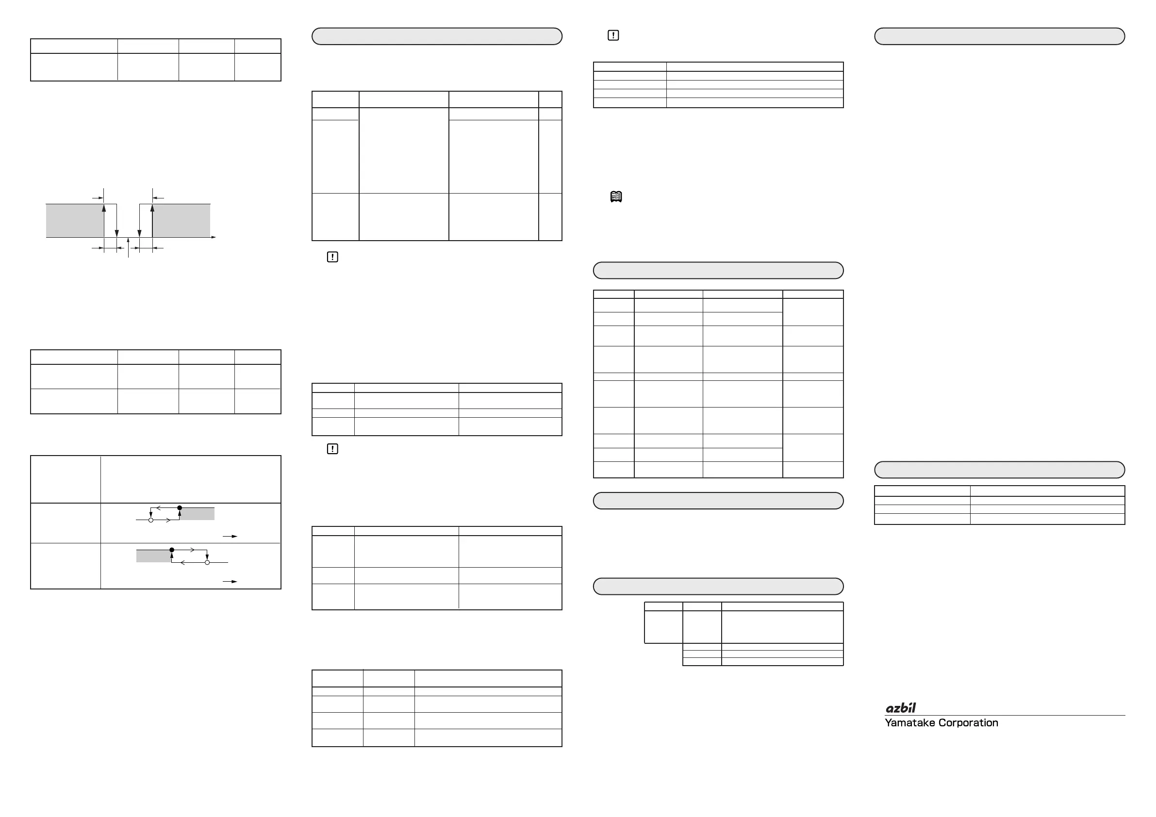
■ Setting the dead zone
This is for setting the dead zone between motor opening and motor
closing in position proportional control. For setting reference, the
dead zone changes when the manual output is at a constant rate.
The value that is obtained when the hunting of the motor stops, is the
minimum value of the dead zone.
If exactly the minimum value is set, the motor is always moving,
causing the service life of the motor to be extremely shortened.
The default setting is 10.0%. With this default value as a reference,
the value can be set correctly by taking the control results and service
life of the motor into consideration.
■ Setting the high/low limit for motor opening
Event output 1 goes ON when the motor opening is above the value set for
the motor opening high limit event (E1). Event output 2 goes ON when the
motor opening is below the value set for the motor opening high limit event
(E2).
This setting is not essential for position proportional control.
The figure below shows the details of the event output action.
The hysteresis (HYS) for ON/OFF is fixed at 0.5%.
■
Operation displays
When the [display] key is pressed, the item that is displayed
changes.
Handling Precautions
• MV(OUT) contains an error of ±0.1% or less caused by factors
like the center of rotation angle and the calculation of the
proportional band.
■ AUTO/MANUAL mode selection
Press the [a/m] key, and "d1.On" or "d1.OF" will start flashing on the lower
display. If the [a/m] key is held down for 1s or longer, the display stays lit
up, the mode switches between AUTO and MANUAL, and the man lamp
goes on or off. When the mode switches from AUTO to MANUAL, the MV
from AUTO mode is retained in manual mode. In MANUAL mode, you can
change the MV (OUT) using the [<], [ ] and [ ] keys.
The table below shows the difference between the two modes.
Handling Precautions
• When power is turned on, the AUTO/MANUAL mode that was
active before power off is retained. However, if the mode
before power off was MANUAL mode, the MV(OUT) is 0.0%
regardless of its value before power off.
■ Multi-Status display
There are three types of display status depending on the condition.
■ Forced opening/closing
You can change the status of the control output (on the OPEN side or CLOSE
side) according to the status of digital input 1 (DI1: between terminals 21 and
24) and digital input 2 (DI2: between terminals 20 and 24).
Handling Precautions
• The table below shows the priority of control output (on the
OPEN side/CLOSE side).
■ Estimated position proportional control
When any motor feedback input failure is detected due to a break in the
Y/T/G lines for motor feedback input or deterioration of motor
potentiometer, estimated position proportional control operates. If the motor
feedback input failure is cleared, the normal position proportional control
resumes. Event output 3 is ON during estimated position proportional
control; it is OFF in other cases.
Note
If estimated position proportional control is activated with a high
frequency, the probable causes are:
• Auto adjustment was not implemented or failed.
• Deterioration or insufficient resolution of the motor potentiometer.
• Connection failure of the motor feedback input.
Cleaning: When cleaning the RN748, use a soft and dry cloth.
Parts replacement: Do not replace the parts.
Fuse replacement: When replacing the fuse, make sure that the replacement fuse
complies with all applicable safety standards:
IEC127, delayed cutoff speed type (T), rated voltage 250V, rated
current 0.5A.
● Input
DC current: 4 to 20mA
Sampling cycle: 100ms
Indication accuracy: ±0.1%FS±1digit (at ambient temperature 23±2°C)
Input impedance: Max. 100Ω
Burnout indication: Down scale + AL02
Allowable input current: Max.30mA
Allowable input voltage: Max.4V(a higher voltage might cause device failure)
● Digital input
Input type: Dry contact or open collector
Allowable ON contact resistance
: Max.250Ω
Allowable OFF contact resistance
: Min.100kΩ
Allowable ON residual voltage: Max.1.0V
Terminal current (ON): Approx.7.5mA (in case of short circuit).
Approx.5.0mA (in case of contact resistance 250Ω)
Minimum hold time: 200ms or more
● Motor feedback potentiometer input
allowable resistance: 100 to 2500Ω
Detection of line break: Displays AL07.
● Motor drive relay output
contact rating: 250Vac 8A (resistive load)
Life: Min. 120,000 operations
Min. switching specifications
: 24V dc, 40mA
● Event relay outputs (ev1 to 3)
contact rating: 250Vac/30Vdc 2A (resistive load)
Life: Min. 100,000 operations
Min. switching specifications: 5V, 10mA (reference value)
● Environmental conditions
• Operating conditions
Ambient temperature: 0 to 50°C (gang-mounted: 0 to 40°C)
Ambient humidity: 10 to 90%RH (non-condensing)
Rated power supply voltage: 100 to 240Vac, 50/60Hz
Power supply voltage range: 85 to 264Vac, 50/60±2Hz
• Transport conditions
Ambient temperature: –20 to +70°C
Ambient humidity: 10 to 95%RH (non-condensing)
● Other specifications
Power consumption: Max. 12VA
Insulation resistance: 20MΩ min. by 500Vdc megger between power terminal
and secondary terminal
Dielectric strength: 1500Vac for one minute between power terminal and
secondary terminal
Inrush current at application
of power: Max. 20A
Non-detected power failure
time: Max. 20ms
Altitude: Max. 2,000m
Mass: Approx. 250g (with the dedicated mounting bracket)
Terminal screw tightening torque:
0.4 to 0.6N•m
Applicable standards: EN61010-1, EN61326
Overvoltage category: Category II (IEC60364-4-443, IEC60664-1)
Allowable pollution degree: Pollution degree 2
<
<
Alarm code table
Maintenance
Model selection table
Alarm code Failure name Cause Corrective action
AL0 1 Input failure Sensor line break, incorrect Check wiring
(over range) wiring
AL02 Input failure Sensor line break, incorrect
(under range) wiring
AL07 MFB input failure Motor line break, incorrect Check wiring or
wiring confirm the MFB
input.
AL 10 Motor adjustment failure Motor line break, incorrect Check wiring,
wiring, motor power supply confirm the motor
failure. power supply,
readjustment.
AL70 A/D conversion failure Defective A/D converter Replace unit.
AL95 Parameter failure • Power turned OFF while • Restart the system.
fixing data • Reset data or replace
• Data corrupted due to unit.
noise, etc. (AL95/97: setting
AL96 Adjustment data failure • Power turned OFF while data, AL96/98:
fixing data adjustment data)
• Data corrupted due to • Replace unit
noise, etc.
AL97 Parameter failure Data corrupted due to noise,
(RAM area) etc.
AL98 Adjustment data failure Data corrupted due to noise,
(RAM area) etc.
AL99 ROM failure ROM (memory) error • Restart the system.
• Replace unit.
Item Indication Contents Initial value
Dead zone
c58
0.5 to 25.0% 10.0%
Operation
Display mode
Upper display Lower display
out lamp
Input (IN) Input value (IN) OFF state OFF
MV (OUT) Range: -10.0 to 110.0% MV (OUT) Lit
Setting: disable Range: -10.0 to +110.0%
Setting: disable in AUTO
mode (display does not
flash.)
Setting: enable in
MANUAL mode (display
flashes)
Motor opening
Fb(Fixed display) Motor opening (MFB) OFF
(MFB) Range: -10.0 to +110.0%
Setting: disable (for
estimation, flashing
value from 0.0 to 100%
AUTO mode MANUAL mode
MV (OUT) Changes with the input (IN) Can be changed manually on the
MV (OUT) display
man lamp OFF Lit
Display just Input (IN) display MV (OUT) display
after switching
Priority Condition Display status
Priority 1 Forced operation of control The whole display blinks.
output (on the OPEN side or
CLOSE side) by digital input
1/2 (DI1/2)
Priority 2 Conditions other than the above, The lighted portion moves
but an alarm occurring. alternately right and left.
Priority 3 Conditions other than the above MV (OUT) is displayed in a bar
graph in which one LED lights
up for every 10%.
Digital input 1 Digital input 2
Control output (on the OPEN side/CLOSE side) status
(DI1) (DI2)
OFF OFF Normal operation
ON OFF Forced open action (forced ON on the OPEN
side; forced OFF on the CLOSE side)
OFF ON Forced close action (forced OFF on the OPEN
side; forced ON on the CLOSE side)
ON ON Halt (forced OFF on the OPEN side; forced
OFF on the CLOSE side)
Priority Control output (on the OPEN or CLOSE side) status
Priority 1 (top priority) Forced ON/OFF operation by digital input 1/2
Priority 2 Auto adjustment
Priority 3 MANUAL mode
Priority 4 Normal position proportional control
Basic model No.
Additions Specifications
RN748A00 Size 48 x 96 mm
100 to 240 Vac
Motor drive relay output, MFB is added
3 event relay outputs
3 digital inputs
00 No additional treatment
D0 Inspection certificate provided
Y0 Complies with traceability certification
Specifications
Accessories and optional parts
Name Model No.
Mounting bracket 81409654-001 (Accessory)
Hard cover 81446915-001
Terminal cover 81446912-001
E3
Specifications are subject to change without notice. (08)
Advanced Automation Company
1-12-2 Kawana, Fujisawa
Kanagawa 251-8522 Japan
URL: http://www.azbil.com
1st Edition: Issued in Apr. 2005
9th Edition: Issued in Nov. 2008 (A)
 Loading...