6
AB-6600
Installation
CAUTION
Use this product under the operating
conditions (for temperature, humidity,
power, vibration, shock, mounting direction,
atmosphere, etc.) listed in the specications.
Failure to do so might cause fire or device
failure.
Installation and wiring must be performed
by qualied personnel in accordance with all
applicable safety standards.
Install the product referring to Figure 7., 8., and 9.
•
If the temperature sensor is attached at higher
position than the main unit, part of the capillary
tube should be lower than the main unit.
Water made by condensation etc. may enter the
main unit to cause a short circuit, re, or failure.
•
If the product is installed outdoors, place it in a
plastic box.
Note: The waterproof cover (Model Q615) is not applicable for this
product.
z
Prohibitions for installing this product
Do not install the product in the following environments.
Doing so might cause malfunction of the device or device
failure in a short period of usage.
•
Where special chemicals or corrosive gas (such as
ammonia, sulfur, chlorine, ethylenic compound, acids,
etc.) exist.
•
Where water droplets or excessive damp air exists.
•
Where condensation is made on the product.
•
Where exposed to direct sunlight or high temperature.
•
Where vibrations or shocks are applied.
•
Where dust or particles will not easily enter into the
product.
z
Cautions for installing this product
•
Mount the the temperature sensor where representative
temperature of the measuring object can be measured.
•
Do not mount the temperature sensor in locations such
as the following.
Temperature may not be correctly measured.
•
Where exposed to warm or cold wind directly.
•
Where air stagnates or there is a draft.
•
Where water level changes largely.
•
Where the temperature sensor cannot be securely
mounted.
•
Where unauthorized persons can have easy access.
•
Secure space around the product for maintenance.
z
Installation procedure
IMPORTANT
•
Do not twist or sharply bend the capillary
tube.
•
Do not leave the cover for the unit and
terminals detached.
Mount the thermostat with the screws through 3
mounting holes provided on its rear side to a wall or
panel.
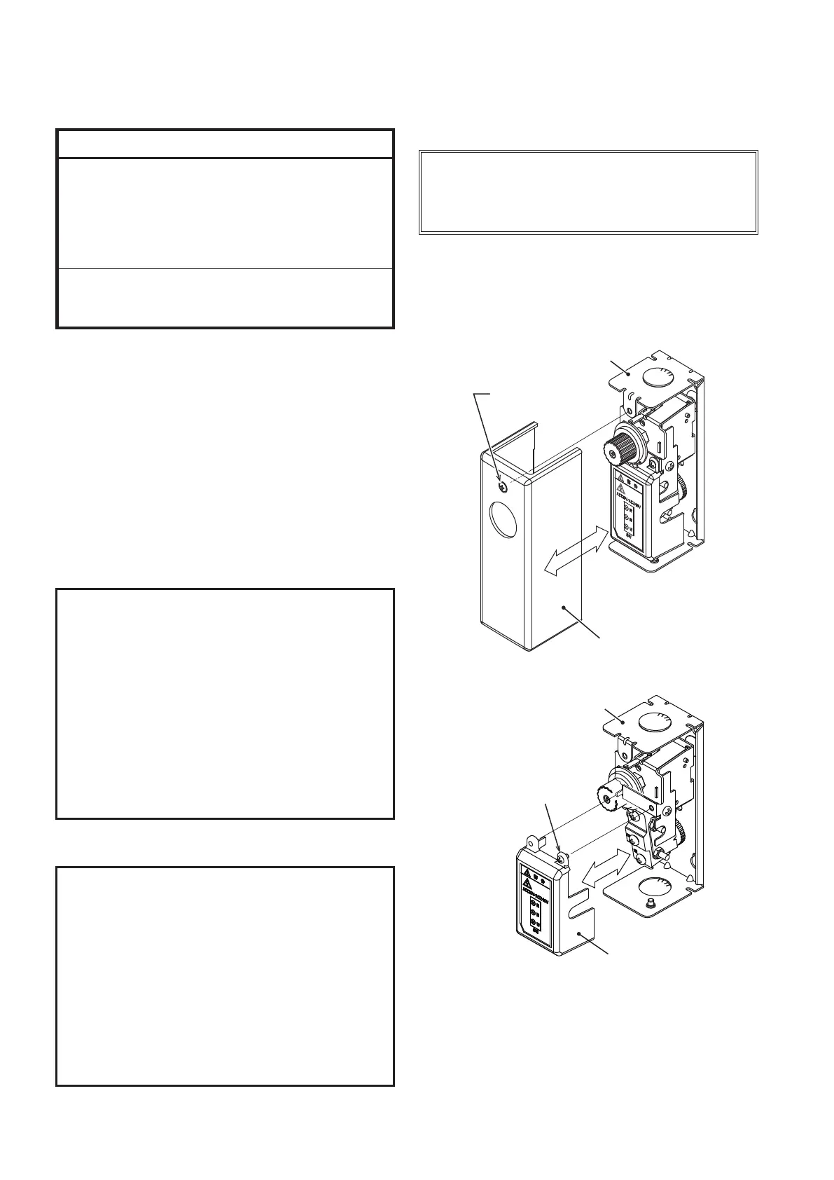
Detach the front cover and the terminal cover
before mounting the thermostat.
Figure 5. Attaching/detaching the front cover
Figure 6. Attaching/detaching the terminal cover
Front cover
mounting screw (x1)
Front cover
Main unit
Terminal cover
mounting screw (x1)
Main unit
 Loading...