1ª 10155 ES 9 - 2009
31
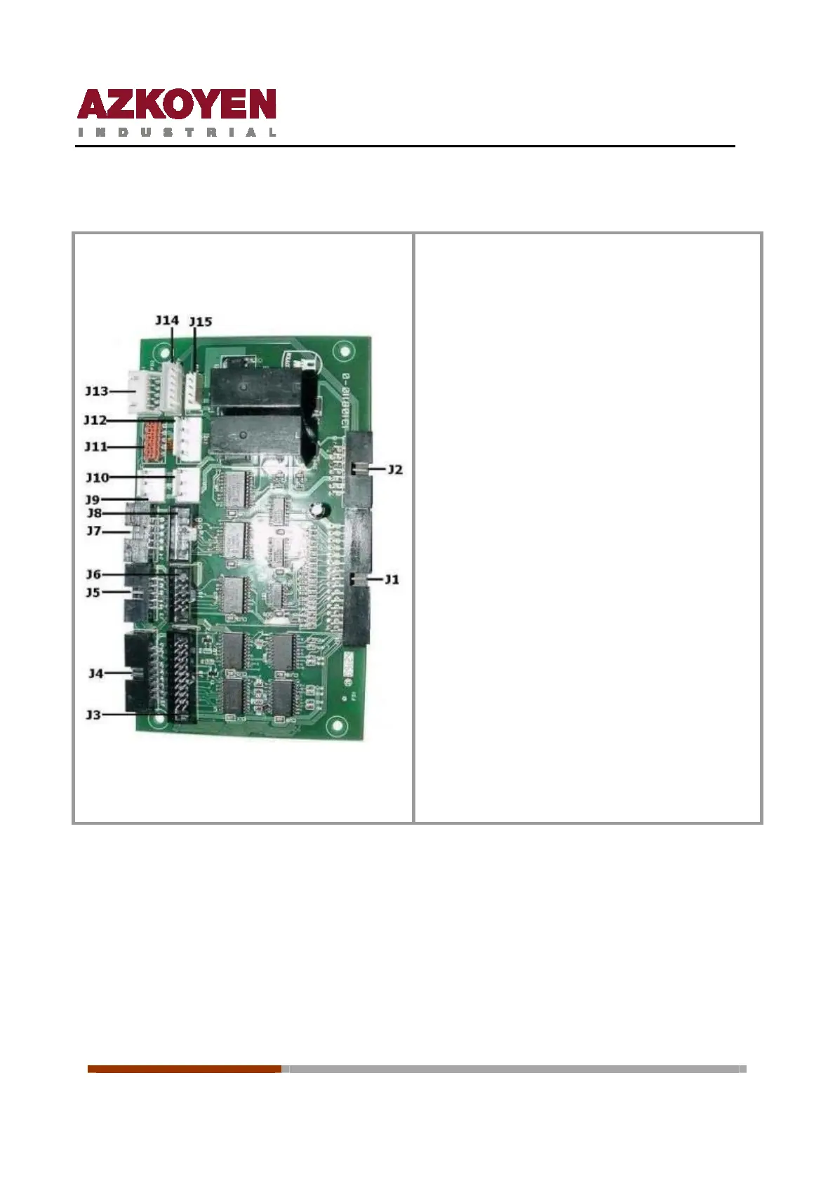
15.3 I/O board
Connectors J1 and J2: communicate the I/O
board with the Rack
Connector J3: not used
Connector J4: establishes communication with
the keyboard control board
Connector J5: establishes the communication
with the motor board on the central grid. (Triple
Machines)
Connector J6: establishes communication with
the motor board on the half channels.
Connector J7: establishes communication with
the motor board on the door. (Double and triple
machines)
Connector J8: establishes communication with
the motor board in the cabinet.
Connectors J9 and J10: power supply of +5v,
+12v and GND for the control board keyboard
Connector J11: establishes communication
with the control board Combo Tower.
Connector J12: power supply of system
peripherals MDB. Note reader, change giver etc.
Connector J13: establishes communication
with RF Receiver.
Connectors J14: not used
Connector J15: establishes communication
with the microswitch detector open door and
the microswitch for interior illumination
15.4 Control board
The control board, with Flash technology, is inserted in the Rack next to the I/O board; its
function is to control the machine and its peripherals. It has two parts:
Ô The circuit that contains the micro-controller (MCF5206e) and the flash memory
(29LV400 4 Mbit).
Ô The circuit that contains the RAM memory (68AW511 of 512KBytes) and the eeprom
memory (24C64 of 64 Kbit).
 Loading...