WWW.BALTIMOREAIRCOIL.COM
36
Resonant Speed Identification Procedure
Thereareseveralcharacteristicfrequenciesatwhichvibrationlevelsmayresonatewith
unitstructuralcomponents.Theseincludefanspeed,motorspeed,bearingfrequency,and
bladepassfrequency.Withintheoveralloperatingspeedrangeofaunit,itisnotunusual
foroneormoreofthesecharacteristicfrequenciestoexcitethestructuralcomponents
overrelativelysmallspeedrangesandcreateanincreaseinvibrationlevels.Ifthevibration
levelsareexcessiveattheseresonantspeeds,theyneedtobelockedouttopreventthe
VFDfromoperatingthemotoratthesespeeds.Thefollowingproceduredescribeshowto
identifythelockoutspeedranges:
• EnsuretheVFDthatcontrolsthefanmotorisoff,andthepowertothemotorcircuitis
lockedout.
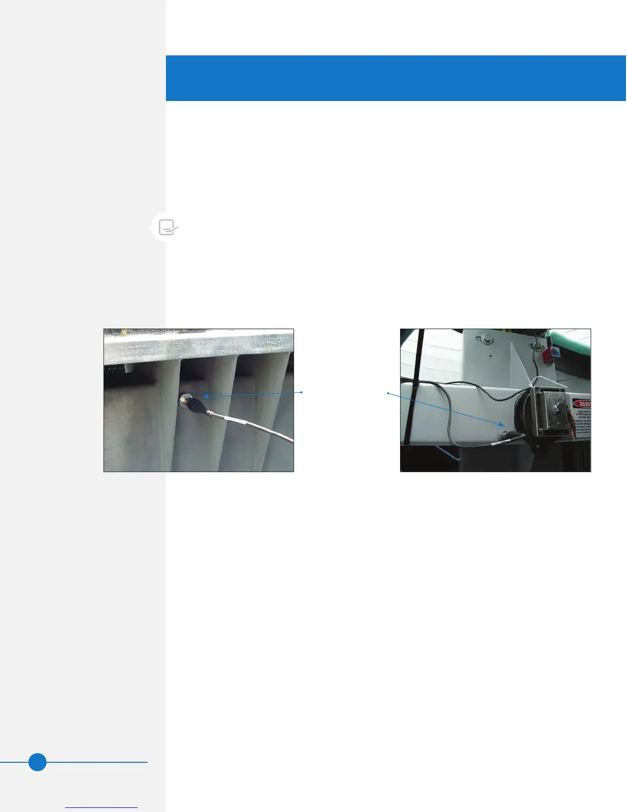
• Dependingonthetypeofdrivesystem(gearorbelt),Attachtheaccelerometer
(providedbyothers)ontotheboxbeamasshowninFigure 11a or 11b.The
accelerometershouldbelocatedawayfromthecenteroftheweboftheboxbeam,
suchthatthecenterlineoftheaccelerometerisabout1inchfromtheupperorlower
edge,asshown.
NOTE: The resonant speed
identification procedure must be
performed at start-up for units with
VFDs.
• Connectthesignalwirefromtheaccelerometer(providedbyothers)tothevibration
analyzer(providedbyothers).Besuretorouteandfastenthewiresothatitwillnot
contactanyrotatingpartsinsidetheunitwhenthedrivesystemisoperational.
• Getoutoftheunit,andensurethatthedrivesystemis“allclear”.Removethe
lockoutfromthemotorcircuit.
• WiththeVFDoff,recordthevibrationlevelindicatedonthevibrationanalyzer,and
conrmthatitisverylow(onlypickingupambientvibration).Recordthisoverall
vibrationlevel(0-peak)ininchespersecond(ips).Iftheambientvibrationlevel
isgreaterthan0.35ips,identifyandcorrectthecauseofthevibration.Itcould
bevibrationtransmittedfromanothersource,instrumentationmalfunction,radio
frequencyinterference,etc.Ifthecauseisvibrationtransmittedfromanothersource,
andthatsourcecannotbeisolatedorturnedoffforthedurationofthemeasurements,
notethesourceandmagnitudeofthevibrationbeforecontinuing.
• Afteritisconrmedthatthedrivesystemis“allclear”andtheunitaccessdoorsare
closed,turntheVFDon,andverifythatthefanisturninginthecorrectdirection.
• UsingtheVFD,slowly(about1RPMincreaseeveryvetotenseconds)adjustthe
motorspeedfromthelowestlimittofullspeedwhilemonitoringthevibrationlevels.
Recordtheoverallvibrationlevelsatregularintervalsifdesired.
Figure 11b. Accelerometer Location - Belt Drive
Correctaccelerometer
location,1”fromthe
edgeoftheboxbeam
Figure 11a. Accelerometer Location - Gear Drive