BACHMANN EUROPE PLC
H0 1:87 19
Your model as an AC variant
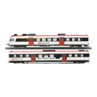
If you have decided on running your LILIPUT model using a central rail alternating current
system, please observe the following: This model has a digital decoder installed (ESU
Lokpilot) which can be used to power your vehicle either on an analogue basis ( 16 volt
AC ) or digitally. Please consult the instruction sheet supplied by ESU for details on how
the decoder works. To collect current from the rail between traction rails, a slider has been
installed on each of the articulated bogies of the end units. ( Fig. 8 ) shows the installed
slider and ( Fig. 9 ) shows the slider installed with the retaining bracket ( R ). The retaining
bracket snaps simply into two clip-in lugs. When taking apart, please press the retention
arm ( S) slightly outwards using a small screwdriver. Naturally the wheel profile of the wheel
sets has also been adapted to the track system commonly in use.
The alternating current version has a board with four switches located in the roof area of
railcar unit A. ( Fig. 10 ) shows the position of the individual switches as well as the setting
of the setting positions A or B. The model comes with all four switches in position A. For
the stop function please slide switch S3 and S4 into position B. However, please note that
the stop function is not possible in overhead operation with pantograph (S2 in position B).
S1 must be in position B for digital operation. The interior lighting is turned on and off here
with the decoder.
Figure 8 Figure 9
R
S
R
Figure 10 see next page
 Loading...