Please note that the function outputs on the decoder AUX3 and AUX4 must have the follo-
wing CV settings:
Decoder type V3.0: CV117 = 15, CV118 = 15, CV129 = 32, CV132 = 16, CV135 = 32,
CV138 = 16
Decoder type V4.0: CV013 = 009, CV049 = 017, CV052 = 016, CV266 = 032, CV282 =
016, CV298 = 032, CV314 = 016
These settings have already been undertaken on the decoder installed by us.
For all other operating information please consult the chapters on coupling the units, put-
ting into operation or looking after your model.
Circuit diagram
For all those desiring more information, we have enclosed the complete circuit diagram for
the car units and the power systems (see pages 9 -12).
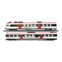
( Fig.11 ) shows the circuit diagram of car unit A in the DC version. For the AC version
please consult ( Fig. 12 ).
The circuit diagram for car unit B in both power systems (DC + AC) is shown in ( Fig. 13 ).
The intermediate car units C, D, E ... are the same in all versions and are shown
in ( Fig. 14 ).
 Loading...