EasyManua.ls Logo

Bachmann Ivatt Mogul 2-6-0 User Manual

Bachmann Ivatt Mogul 2-6-0
22 pages
To Next Page IconTo Next Page
Page #1 background imageLoading...
Page #1 background image
Bachmann Ivatt Mogul 2-6-0 - Assembly instructions
Introduction and general notes
We have had been many requests to produce an add-on kit for the Bachmann Ivatt Mogul. We felt that
there we could make little or no improvement above the footplate because that part of the model is
excellent, but we could make a worthwhile improvement in the detail and running of the chassis.
This kit has overlays for use in 00, EM and 18.83 gauges; all parts are included to enable construction,
if required, for a sprung locomotive chassis (bearings for the chassis are not included) and sprung
tender chassis, although some modifications may be necessary for closer than scale frames and tight
curves, and to allow for over scale wheel flanges. The basic design/overlays follow the prototype as
closely as possible and therefore clearances in some cases are tight.
The design uses overlays with plasticard packing to achieve the correct chassis spacing (note - white
has been used for better illustration here).
The Bachmann chassis is 11mm wide, not including the boss around the axle slot.
The model depicted in the photographs is built to 18.83 standards and to pack out the chassis overlays
0.60” 1.5mm white plasticard was used. The overall chassis width with overlays is 15.25mm plus
approximately 0.125mm for the etched rivets on the second overlay.
Brassmasters 1/8” bearings were used with the thicker boss to the outside, washers were used as
required there is little or no end float on the front driving axle. The remaining axles had approximately
0.5mm end float.
The model is built with 1/8” axles and a High Level HighFlier gearbox and 13.5mm x 26.5 mashima flat
can motor (available from Chris Gibbon-High Level Kits). Whilst it is perfectly alright to build the chassis
with the supplied motor and gearbox we felt we wanted to take the model to a stage further.
During construction, it was found that using the supplied etched springs the pick-ups on the Bachmann
keeper plate would no longer fit and new pick-ups had to be made. (See photo-pull rods fitted)
There are many options available to the modeller with this kit from a sprung chassis to fixed axles and
we recommend a careful study of your requirements before starting construction.
Alan Gibson produces a complete drop in wheel set; these come with a direct replacement 3mm axle
used by Bachmann. However also available from Alan Gibson is the correct driving wheel size (1/8”
axle) along with pony and tender wheels. Another option is Exactoscale 1/8” or 3mm bearings and
springs; these are not described here but with some minor modifications to the solid Bachmann chassis
will fit the chassis overlays.
Etchings
We have used nickel-silver throughout, since it is much easier than brass to solder and to paint. All
bends are on the half etch line except where otherwise stated.
Wherever possible we have included spares of some components to allow for those parts which
generally hide in the carpet.
Please remove all etched cusp from the parts to obtain a good fit and in some cases it is critical the
cusp is removed.
NOTE most rivets on this model are depicted by the use of half etch overlays, but some require
embossing from the rear. Although a rivet embossing tool may be used to form the push-through rivets
the variable spacing sometimes makes this a little difficult. We recommend resting the etch sheet on a
piece of lead flashing (available from builders merchants) or hardboard and embossing with a blunt
compass or needle.
Question and Answer IconNeed help?

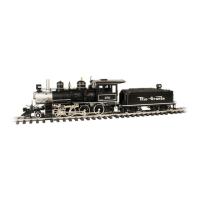
Do you have a question about the Bachmann Ivatt Mogul 2-6-0 and is the answer not in the manual?

Bachmann Ivatt Mogul 2-6-0 Specifications

General IconGeneral
BrandBachmann
ModelIvatt Mogul 2-6-0
CategoryToy
LanguageEnglish

Summary

Introduction and General Notes

Kit Overview and Chassis Design

Details kit gauge compatibility, overlays, chassis width, and design principles.

Running Gear and Motor Options

Information on bearings, axle float, motor, gearbox choices, and wheel sets.

Etching Material and Rivet Application

Guidance on nickel-silver material, bending, cusp removal, and rivet techniques.

Pony Truck Assembly

Pony Truck Frame and Hornguides

Instructions for assembling the pony truck frame, bearing hornguides, and spring guides.

Long Spring Preparation and Fitting

Details on preparing and fitting the long springs and top plate.

Pony Truck Plate Assembly

Spring Wire and Plate Construction

Instructions for preparing spring wire and assembling front and rear plates.

Pony Truck Final Assembly

Guard Iron and Rear Bar Modifications

Instructions for modifying guard irons and assembling the rear pony truck bar.

Chassis Component Removal and Side Frames

Removing Motor, Gears, and Valve Gear

Steps to remove motor, gears, PCB, valve chest, cylinders, and motion plate.

Side Frame Fitting and Preparation

Fitting side frames, cutting plasticard, and preparing coupling rods.

Chassis Frame Overlay and Bearing Installation

Overlay Fitting and Axle Slotting

Fitting chassis overlays, marking, drilling, and opening axle slots.

Bearing and Pin Securing

Checking centre bearings, fitting pins, and securing chassis sides.

Chassis Overlay Pinning and Refinement

Temporary Pinning and Metal Adjustments

Using temporary pins, removing rear metal, and deepening axle slots.

First Overlay Secured

Fixing the first overlay and smoothing pins flat onto the chassis.

Final Bearing and Spring Fitment

Overlay and Bearing Final Check

Fitting both overlays and performing final bearing checks.

Spring Installation and Pickup Clearance

Installing springs, ensuring pickup clearance, and fitting coupling rods.

Pony Truck Integration and Clearance

Coupling Rod Installation

Fitting the coupling rods to the chassis assembly.

Pony Truck Movement Enhancement

Modifying the chassis block for improved pony truck freedom.

Gearbox, Axles, and Pickups

Top Overlay and Gearbox Fitment

Checking top overlay, hornguide straps, and fitting gearboxes.

Axle Reaming and Pickup Construction

Reaming axles and constructing pickups from wire and PCB.

Motor Mount Area Modification

Metal Removal Under Motor Mount

Detailed steps for removing metal from under the motor mount.

Boiler Area Modification and Pickups

Boiler Area Metal Removal

Instructions for removing a small amount of metal from under the boiler area.

Sprung Pickup Installation

Details on fitting the sprung pickups to the chassis.

Brake System Assembly

Brake Lever and Hanger Construction

Folding brake levers and hangers, and drilling for hanger wire.

Brake Shoe and Pull Rod Fitting

Securing brake shoes, fitting pull rods, cross beams, and rear pull rod.

Valve Gear Construction

Connecting Rod and Crosshead Assembly

Assembling connecting rods, crossheads, and initial valve gear parts.

Key Valve Gear Components and Notes

Details on rolling bearings, return cranks, expansion links, and reversing shaft brackets.

Valve Gear Fitting and Cab Details

Temporary Valve Gear Fitment

Temporarily fitting the assembled valve gear to check alignment.

Cab Door Construction and Fitting

Making and fitting the 'U' shaped parts for the cab doors.

Cab Floor and Front Chassis Extension

Cab Floor and Fall Plate Assembly

Fitting the cab floor and fall plates into the cab structure.

Front Chassis Extension and Steps

Modifying chassis extensions and fitting step support plates and steps.

Tender Chassis Construction

Tender Springing and Frame Assembly

Assembling the sprung tender chassis, bearing guides, and frames.

Inner Chassis and Gauge Spacing

Fitting inner chassis, spacers, and stiffening brace for gauge adjustment.

Tender Brakes and Sieve Box

Fitting tender brakes and alternative sieve box designs.

Tender Detailing and Guard Irons

Step and Ladder Fitting

Fitting steps to the tender frame and constructing the ladder.

Rear Guard Iron Shaping

Bending the rear guard irons to the correct shape.

Tender Final Assembly and Details

Brake Levers and Sieve Box Finalisation

Final fitting of brake levers and sieve box on the tender.

Related product manuals