EasyManua.ls Logo

Bailey Infi90 - Final PMU Setup and System Power-Up

Default Icon
68 pages
Print Icon
To Next Page IconTo Next Page
To Previous Page IconTo Previous Page
Loading...
I
E96
506A
INSTALLATION
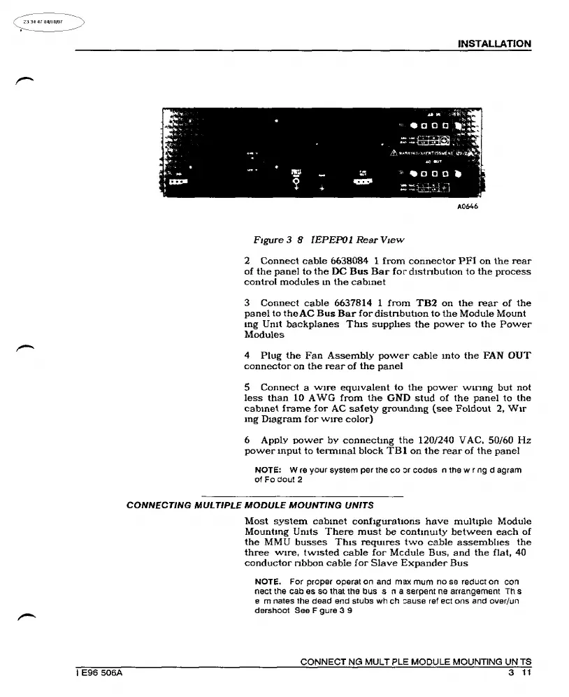
A0646
FJgure3
8
IEPEPOl
RearV1ew
2
Connect
cable
6638084
1
from
connector
PFI
on
the
rear
of
the
panel
to
the
DC
Bus
Bar
for
d1stnbutmn
to
the
process
control
modules
m
the
cabmet
3
Connect
cable
6637814
l
from
TB2
on
the
rear
of
the
panel
to
theAC
Bus
Bar
for
distnbuhon
to
the
Module
Mount
mg
Umt
backplanes
Th1s
supphes
the
power
to
the
Power
Modules
4
Plug
the
Fan
Assembly
power
cable
mto
the
FAN
OUT
connector
on
the
rear
of
the
panel
5
Connect
a
Wire
equivalent
to
the
power
w1nng
but
not
less
than
lO A
WG
from
the
GND
stud
of
the
panel
to
the
cabmet
frame
for
AC
safety
groundmg
(see
Foldout
2,
Wtr
mg
Diagram
for
w1re
color}
6
Apply
pawer
by
connectmg
the
120/240
V
AC,
50/60
Hz
power
mput
to
termmal
block
TBI
on
the
rear
of
the
panel
NOTE: W re
your
system
per
the
co
or
codes
n
the
w r
ng
d agram
of
Fodout2
CONNECTING
MULTIPLE
MODULE
MOUNTING
UNITS
Most
system
cabmet
configurations
have
multiple
Module
Mountmg
Umts
There
must
be
contmmty
between
each
of
the
MMU
busses
This
reqmres
two
cable
assembhes
the
three
Wire,
twisted
cable
for
Mcdule
Bus,
and
the
flat,
40
conductor
nbbon
cable
for
Slave
Expander
Bus
NOTE.
For
proper
opera!
on
and max
mum
nose
reduct
on
con
nect
the
cab
es
so
that
the
bus
s n a serpent ne arrangement
Th
s
e m nates
the
dead
end
stubs
wh
ch
Gause ref ect
ons
and
over/un
dershoot
See F gure 3 9
CONNECT
NG
MULT PLE MODULE MOUNTING UN
TS
3
11
Artisan Technology Group - Quality Instrumentation ... Guaranteed | (888) 88-SOURCE | www.artisantg.com

Other manuals for Bailey Infi90