EasyManua.ls Logo

Bailey Infi90 - Section 4: Operating Procedures; LED Indicators and Status Interpretation

Default Icon
68 pages
Print Icon
To Next Page IconTo Next Page
To Previous Page IconTo Previous Page
Loading...
INSTALLATION
Module
Bus
Cable
(Three
W1re,
Twisted pa1r)
1
Attach
one
end
of
the
cable
to
the
second
column
of
three
tabs
on
the
lower
left
of
the
MMU
backplane
(facmg
from
behmd)
2
Attach
the
other
end
of
the
cable
to
the
f1rst
column
of
three
tabs
on
the
lower
left
of
the
next
MMU
backplane
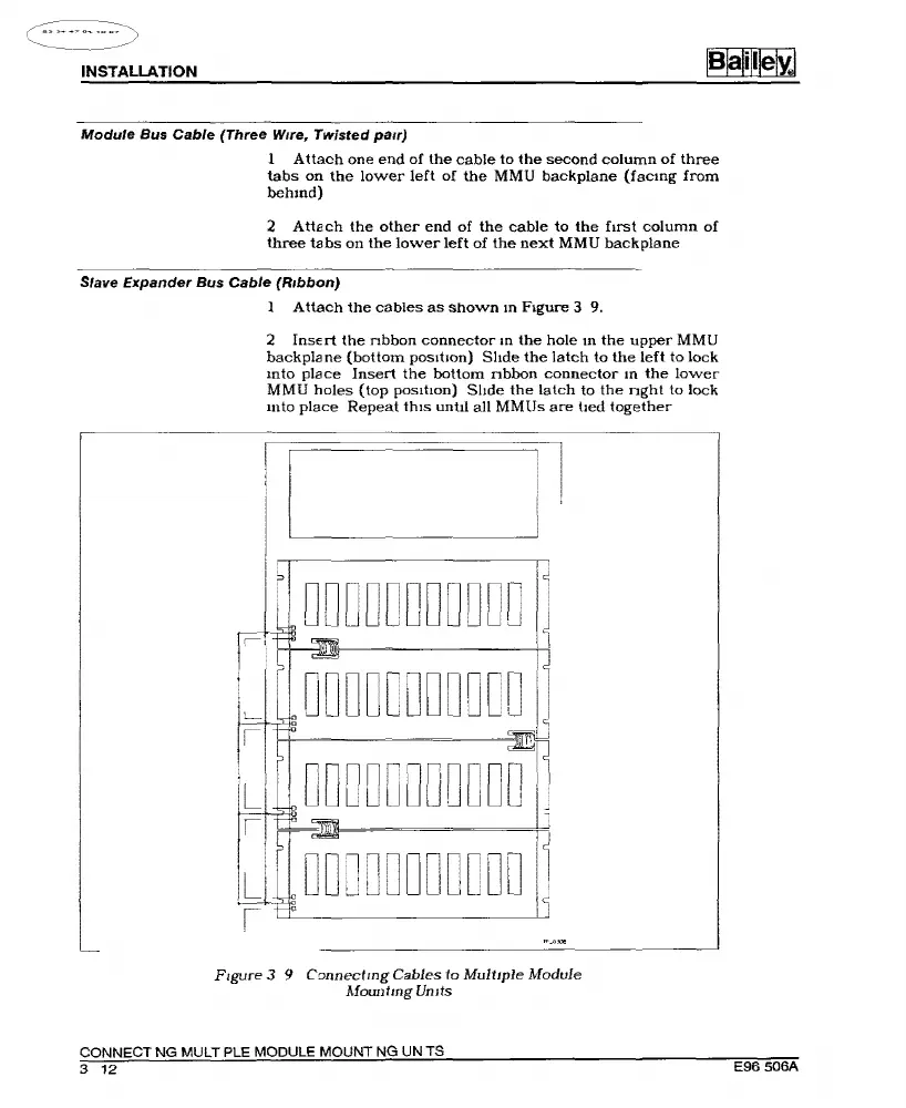
Slave Expander Bus
Cable
(Ribbon)
I
Attach
the
cables
as
shown
m F1gure 3
9.
2
Insert
the
nbbon
connector
m
the
hole
m
the
upper
MMU
backplane
(bottom
pos1hon)
Shde
the
latch
to
the
left
to
lock
mto
place
Insert
the
bottom
nbbon
connector
m
the
lower
MMU
holes
(top
pos1tlon)
Shde
the
latch
to
the
nght
to
lock
mto
place
Repeat
th1s
until
all
MMUs
are
bed
together
li~___j
i:
I p
DDDDDDDDDDD
DDDDDDDDDDD
DDDDDDDDDDD
DDDDDDDDDDD
F1gure
3 9
Connectmg
Cables
to
Multiple
Module
Afountmg
Umts
CONNECT
NG
MULT
PLE MODULE
MOUNT
NG
UN
TS
3
12
E96
506A
Artisan Technology Group - Quality Instrumentation ... Guaranteed | (888) 88-SOURCE | www.artisantg.com

Other manuals for Bailey Infi90