Do you have a question about the Baker Hughes Masoneilan 77-6 and is the answer not in the manual?
Explains the safety alert symbol and defines DANGER, WARNING, CAUTION, and CAUTION (property damage) levels.
Provides information on manual updates, reproduction restrictions, error reporting, and scope of the instructions.
Estimates the product's useful life and factors affecting it, emphasizing maintenance and proper installation.
Details the warranty period, coverage for defects, and Baker Hughes' right to change specifications.
Highlights requirements for qualified personnel, flushing lines, and potential risks from damaged equipment.
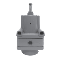
Covers warnings, pressure limits, cleaning, placement, and connection requirements for proper installation.
Specifies requirements for products certified for explosion-proof or intrinsically safe installations.
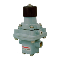
Details the steps for adjusting the lock-up valve setting, including pressure supply, screw adjustment, and final connections.
Emphasizes shutting off supply pressure and relieving spring compression before any maintenance procedures.
Provides step-by-step instructions for disassembling and reassembling the lock-up valve for maintenance.
Guides on inspecting the diaphragm and inlet valve for wear or damage and when to replace them.
Suggests stocking complete units due to high labor costs for internal part replacement.
| Accuracy | ±1% of span |
|---|---|
| Ambient Temperature Range | -40 to 180°F (-40 to 82°C) |
| Supply Pressure | 20 psi (recommended) |
| Output Signal | 3-15 psi (standard) |
| Materials | Aluminum |
| Type | Pneumatic |