PanaFlow Z1G/Z2G
Quick-Start Guide
1100 Technology Park Drive, Billerica, MA 01821, U.S.A.
Telephone: 978-437-1000 or 800-833-9438
Sensing House, Shannon Free Zone East, Shannon, County Clare, Ireland
Telephone: +353 61 470200
916-149, Rev. A
Jun 2018
Installation Instructions (see other side for Electrical Wiring and Programming Instructions)
WARNING! Follow all local safety codes and
regulations for installing electrical equipment and
working with hazardous fluids or flow conditions.
Consult safety personnel to verify all procedures.
WARNING! The PanaFlow Z1G/Z2G Process Gas
Flowmeter can measure the flow rate of many gases,
some of which are potentially hazardous.
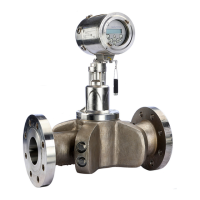
1. Local Mount PanaFlow Z1G/Z2G
Remove the Components from the Shipping Container. The typical PanaFlow
Z1G/Z2G system shown in Figure 1 includes the following items:
Figure 1: Local Mount PanaFlow Z1G/Z2G Process Gas Flow meter
Assembly
Note: For Electrical Connections information See “Making the Electrical
Connections” on page 2.
2. Remote Mount PanaFlow Z1G/Z2G
The typical Remote PanaFlow Z1G/Z2G system shown in Figure 2 includes the
following items:
Figure 2: Remote Mount PanaFlow Z1G/Z2G
3. Remote Mount Connection between FlowCell and Electronics
Figure 3: Remote Mount Wiring Options
3.1 Wiring Configuration options with/without Preamp
Figure 4: Wiring Configurations for Remote Mount Without Preamp
Figure 5: Wiring Configurations for Remote Mount With PreAmp
Note: For Making Remote Mount Connection between FlowCell and Electronics
See Figure 2 to Figure 7.
1- Meter Body with Flanges (material list WCB: LCB: CF8M: CD3MWCuN)
2 - Transmitter Electronics
3 - Magnetic Stylus (for Transmitter Keypad)
4 - Mounting Adapter, Transmitter (for local mount only)
5 - Transducers/Inserts
1- Meter Body with Flanges (material list WCB: LCB: CF8M: CD3MWCuN)
2 - XGM868i Electronics
3 - Electronics Mounting Bracket
4 - Remote Mount Adapter
5 - Haz. Area Certified Remote Cable
6 - Combined Pressure & Temperature Sensor (Optional)