EasyManua.ls Logo

Balboa Water Group BP100G2 - User Manual

Balboa Water Group BP100G2
24 pages
Print Icon
To Next Page IconTo Next Page
Loading...
Template 56377 10-05-12
1
Manufactured under one or more of these patents. U.S. Patents: 5332944, 5361215, 5550753, 5559720, 5,883,459, 6253227, 6282370, 6590188, 6976052, 6965815, 7030343, 7,417,834 b2,
Canadian Patent: 2342614, Australian patent: 2373248 other patents both foreign and domestic applied for and pending. © Copyright 2009 Balboa Water Group.
59267_59268_A 05-13-19
BP100G2 Tech Sheet
Customer: Balboa Water Group
Part Number: 59267 5.5kW 800 Incoloy
59268 4.0kW 800 Incoloy
Custom Box Overlay
Box Overlay Part Number N/A
UL System Model For 5.5kW: BP1-BP100G2-BU
For more information
PLEASE VISIT
UL System Model For 4.0kW: BP1-BP100G2-BS
Software Version ID: M100_230 V48.0
Software Version: 48.0
File Name: BP100_48.0_BP100G2.hex
Configuration Signature: F402B0EF
Eng. Project Number: 5205
Control Panels (See later pages for more information):
spaTouch™2 Any version (version 2.0 or later required for bba™2 fully integrated functionality)
Icon spaTouch™ Any version (version 3.36 or later required for bba™2 fully integrated functionality)
Menued spaTouch™ Any version (version 2.8 or later required for bba™2 integrated functionality)
TP900 Version 3.1 and later (Version 3.13 or later required for bba™)
TP800 Version 3.1 and later (Version 3.13 or later required for bba™; version 4.11 or later required for bba™2 integrated functionality)
TP600 Version 2.7 and later (Version 2.12 or later required for bba™/bba™2 On/O control via menu)
TP400T US Version 2.7 and later (TP400T CE may be used) (Version 2.12 or later required for bba™/bba™2 On/O control via menu)
TP400W US Version 2.7 and later (TP400W CE may be used) (Version 2.12 or later required for bba™/bba™2 On/O control via menu)
Question and Answer IconNeed help?

Do you have a question about the Balboa Water Group BP100G2 and is the answer not in the manual?

Summary

BP100 G2 Tech Sheet

Control Panels

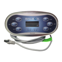
Lists compatible control panels and required software versions for integrated functionality.

System Revision History

Basic Functions Setup

Power Requirements

Details electrical requirements and wiring for 240VAC and 120/240VAC systems.

System Outputs

Hardware Setup

Wiring Diagram

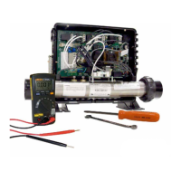
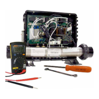
Illustrates the physical connections and component layout for system wiring.

Setup Reference Table

Changing Software Setups with spaTouch Panels

Test Menu Access

Explains how to enter Test Mode for software setup changes on spaTouch panels.

Changing Software Setups with Menued Panels

Test Menu Access

Details entering Test Mode and changing setups on menued panels like TP800/TP900.

Changing Software Setups with TP600;TP400

Test Menu Access

Guide to entering Test Mode and initiating software setup changes on TP600/TP400.

TP600;TP400 Setup Procedure

Equipment Expansion

Expansion Features

Outlines expansion capabilities, default settings, and fuse requirements for added components.

DIP Switch Functions

Fixed-function DIP Switches

Explains the purpose and function of fixed DIP switches for system configuration.

Assignable DIP Switches

Describes the function of assignable DIP switches for various system settings.

Jumper Definitions

Jumper Configuration Details

Details the settings and functions for specific jumpers (J109, J30, J31, J24).

Replacement Parts

Component Identification

Lists part numbers for PCBs, heaters, sensors, and fuses for replacement.

BP100 Configuration Options - General Features

General Features

Defines general system features, timers, and cycle settings.

BP100 Configuration Options - Temperature Features

Temperature Features

Details temperature display options, conversion, and set point ranges.

BP100 Configuration Options - Time Features

Time Features

Configures filter cycle start times, durations, and light cycle settings.

BP100 Configuration Options - Reminder Features

Reminder Features

Configures system reminders for maintenance tasks like filter cleaning and GFCI testing.

BP100 Configuration Options - Special Features

Special Features

Defines special features like amperage rules, drain/demo modes, and menu styles.

TP900 Panel Configuration

Button Layout Table

Details the button assignments for different setups on the TP900 control panel.

TP800 Panel Configuration

Button Layout Table

Lists button assignments for various setups on the TP800 control panel.

TP800 Panel Configuration

Panel Screen Layouts

Displays visual layouts for the Spa Screen and Shortcuts Screen of the TP800 panel.

TP600 Panel Configuration

Button Layout Table

Details the button configurations for Setups 1&2 and Setups 3&4 on the TP600 panel.

TP400 Panel Configuration

Button Layout Tables

Outlines button assignments for TP400T and TP400W panels across different setups.

Overview

The Balboa Water Group BP100G2 is a spa control system designed to manage various functions of a hot tub, including pumps, heater, ozone, and lighting. It is available in two main configurations: Part Number 59267 with a 5.5kW 800 Incoloy heater and Part Number 59268 with a 4.0kW 800 Incoloy heater. The system supports a range of control panels, including spaTouch™2, Icon spaTouch™, Menued spaTouch™, TP900, TP800, TP600, TP400T US, and TP400W US, each with specific software version requirements for full functionality.

Technical Specifications:

Power Requirements:

  • 240VAC, 50/60Hz, 48A: Class A GFCI-protected service (Circuit Breaker = 60A max.), 4 wires [hot, hot, neutral, ground].
  • 120/240VAC, 50/60Hz, 16/40A: Class A GFCI-protected service (Circuit Breaker = 20/50A max.) for Setups 3 & 4 only, 3 or 4 wires [hot, hot (optional), neutral, ground].
    • Note: 120V specification is for wall-mount GFCI/breaker; GFCI cord limits service to 12A with a 15A breaker.
  • BP systems automatically detect 50Hz vs 60Hz. However, different BP systems are used for UL vs CE territories due to other power differences.

System Outputs:

  • Pump 1 (240VAC):
    • 2-Speed, 12A max, 15-minute timer (30-minute timer for P1 Low in non-circ Setups 2 & 4 only).
    • Heater pump in Setups 2 & 4, must deliver 20 GPM through heater.
    • 1-Speed in Setups 1 & 3.
  • Pump 2 (240VAC):
    • 1-Speed, 12A max, 15-minute timer.
    • Unused in Setups 3 & 4.
  • Circ Pump (240VAC):
    • 1-Speed, 2A max, Programmable Filtration Cycles + Polling.
    • Heater pump in Setups 1 & 3, must deliver 20 GPM through heater.
  • Ozone (240VAC):
    • 0.5A max.
    • Slaved to Circ Pump in Circ Setups and to Pump 1 Low in Non-Circ Setups.
  • Spa Light (10VAC):
    • On/Off, 1A max, 240-minute timer.
  • A/V (Stereo) (120VAC):
    • Hot, 3A max, Always on.
  • Heater:
    • 5.5kW @ 240VAC (approx 1.4kW @ 120VAC).
    • 4.0kW @ 240VAC (1.0kW @ 120VAC).
  • Note: Pump 1, Circ Pump, and Ozone must be the same voltage. With 120VAC power input (Setups 3 & 4 only), Pump 1, Circ Pump, and Ozone must all be 120V.

Control Panels and Software:

  • Software Version ID: M100_230_V48.0 (Version 48.0).
  • File Name: BP100_48.0_BP100G2.hex.
  • Configuration Signature: F402B0EF.
  • spaTouch™2: Any version (2.0 or later for bba™2 fully integrated functionality).
  • Icon spaTouch™: Any version (3.36 or later for bba™2 fully integrated functionality).
  • Menued spaTouch™: Any version (2.8 or later for bba™2 integrated functionality).
  • TP900: Version 3.1 and later (3.13 or later for bba™).
  • TP800: Version 3.1 and later (3.13 or later for bba™; 4.11 or later for bba™2 integrated functionality).
  • TP600: Version 2.7 and later (2.12 or later for bba™/bba™2 On/Off control via menu).
  • TP400T US/CE: Version 2.7 and later (2.12 or later for bba™/bba™2 On/Off control via menu).
  • TP400W US/CE: Version 2.7 and later (2.12 or later for bba™/bba™2 On/Off control via menu).

Usage Features:

System Setups:

The BP100G2 system is shipped in Setup 2 (None for Circ Pump, 2-Speed for Pump 1, 1-Speed for Pump 2, °F Temp Scale). There are four predefined setups:

  • Setup 1: Programmable Filtration + Polling (Circ Pump), 1-Speed (Pump 1), 1-Speed (Pump 2), °F Temp Scale.
  • Setup 2: None (Circ Pump), 2-Speed (Pump 1), 1-Speed (Pump 2), °F Temp Scale.
  • Setup 3: Programmable Filtration + Polling (Circ Pump), 1-Speed (Pump 1), None (Pump 2), °F Temp Scale.
  • Setup 4: None (Circ Pump), 2-Speed (Pump 1), None (Pump 2), °F Temp Scale.

Changing Software Setups (Service Technician ONLY):

  • Test Menu Access: Move DIP Switch 1 (on S1 on the Main circuit board) to ON while the system is running. The system will enter Test Mode, indicated by "T" after the temperature. Moving DIP Switch 1 to OFF exits Test Mode.
  • Icon-Driven Panels (spaTouch™):
    1. Enter Test Mode.
    2. Navigate to "Settings" then "Test" then "Setup#".
    3. Use Up/Down icons to select the desired Setup Number.
    4. Press the Check Mark icon to confirm and restart the spa.
    5. A "settings have been reset" message may appear; press "Clear" to dismiss.
  • Menued Panels (TP800/TP900/spaTouch™ Menued):
    1. Enter Test Mode.
    2. Under the TEST Menu, select "Setup".
    3. Change the Setup from 1 to the desired number.
  • TP600/TP400 Panels:
    1. Enter Test Mode.
    2. Exit Priming Mode by pressing any Temperature button ONCE when "RUN PMPS PURG AIR" is displayed.
    3. Within 1 minute, press Warm*, Light, Warm, Warm, Warm, Warm. Continue pressing Warm until the desired Setup Number (S-01, S-02, etc.) is displayed.
    4. Press Light once to reset the system with the new Setup.
    5. Move DIP Switch 1 to OFF.
    • Note: If the control panel has a single Temp button instead of a Warm (Up) button, use the Temp button.

Configuration Options (Default Settings):

  • General Features:
    • Pump 1 in Filter Cycle (Circ Only): No
    • Pump 1 Low Timer: 30 Minutes (applies in non-circ Setups)
    • General Pump Timer: 15 Minutes
    • Blower Timer: 15 Minutes
    • Mister Timer: 15 Minutes
    • Light Timer: 240 Minutes
    • Circ (when enabled): Programmable + Polling
    • Cleanup Cycle: 30 Minutes
    • Cleanup as Preference setting: Yes
    • Ozone: With Heater Pump* (can be Circ Pump or Pump 1 Low)
    • Ozone Suppression: OFF
    • Pump Purge: 60 Seconds
    • Blower Purge: 30 Seconds
    • Mister Purge: 5 Seconds
    • Purge Type: Serial - Pumps at lowest speed
  • Temperature Features:
    • Temperature Display: °F (system converts °F to °C dynamically)
    • Hi-Range Min. Set Temp: 80°F
    • Hi-Range Max. Set Temp: 104°F
    • Hi-Range Default Temp*: 100°F
    • Lo-Range Min. Set Temp: 50°F
    • Lo-Range Max. Set Temp: 99°F
    • Lo-Range Default Temp*: 70°F
    • Freeze Threshold: 44°F
    • Freeze Type: Rotating - Pumps at Lowest Speed
    • Temp Lock Type: Temp + Settings
    • Note: Items marked with an asterisk (*) may be changed by end-user (if enabled).
  • Time Features:
    • Time Format*: 12 Hour
    • Filter 1 Start Hour*: 20:00 (8:00 PM)
    • Filter 1 Duration*: 2 Hours
    • Filter Cycle 2 Default*: OFF
    • Filter 2 Start Hour*: 08:00 (8:00 AM)
    • Filter 2 Duration*: 15 Minutes
    • Light Cycle: Disabled
    • Light Cycle Default*: OFF
    • Light Cycle Start Hour*: 21:00 (9:00 PM)
    • Light Cycle Duration*: 15 Minutes
    • Cooling Time A: 1 Minute (for electric heaters)
    • Cooling Time B: 5 Minutes (for gas heaters)
    • Note: Items marked with an asterisk (*) may be changed by end-user (if enabled).
  • Reminder Features:
    • Reminders Shown*: Yes
    • Check pH: OFF
    • Check Sanitizer: OFF
    • Clean Filter: 30 Days
    • Test GFCI: OFF
    • Drain Water: 100 Days
    • Change Cartridge: OFF
    • Clean Cover: OFF
    • Treat Wood: OFF
    • Change Filter: 365 Days
    • Note: Items marked with an asterisk (*) may be changed by end-user (if enabled).
  • Special Features:
    • Special Amperage Rule A: No Limitation
    • Special Amperage Rule B: No Limitation
    • Drain Mode: Disabled
    • Demo Mode: Disabled
    • GFCI Trip: Enabled
    • Automatic GFCI Test: Disabled
    • Ozone Slaved to Heater Pump: Yes
    • Dual Voltage Heater: Always Input Voltage
    • Safety Suction: Disabled
    • Menu Style: Standard Menus when DIP switch A7 is OFF; Simplified Menus when DIP switch A7 is ON.

DIP Switch Functions:

  • A1 (Test Mode): Normally Off.
  • A2 (Add 1 HS Pump/Blower with Heater): ON position.
  • A3 (Add 2 HS Pumps/1 HS Pump & Blower with Heater): ON position.
    • Note: A2 and A3 determine when the heater is disabled based on the number of high-speed devices running. A2/A3 all off means no heat with any high-speed pump or blower.
  • A5 (Special Amperage Rule B): ON position. OFF position enables Special Amperage Rule A.
  • A6 (Persistent Memory Reset): Used to restore factory settings when spa powers up.
  • A4 (Cooling Time B/A): ON for 5-minute cooldown (gas heaters); OFF for 1-minute cooldown (electric heaters).
  • A7 (Simplified/Regular Menus): ON for Simplified Menus on TP400/TP600 (do not use with graphic panels); OFF for Regular Menus on TP400/TP600 (compatible with all panels).
  • Undesignated switches are not assigned a function.

Jumper Definitions:

  • J109 (GFCI Test/Trip Enable/Disable): Must be enabled in software.
  • J30: Do Not Use.
  • J31 (Heater Voltage): Jumper on 1 pin for 120V heater; Jumper on 2 pins for 240V heater.
  • J24 (Heater Voltage): Jumper on center two pins for 240V heater; Two jumpers (one on left 2 pins, one on right 2 pins) for 120V heater.

Maintenance Features:

HiPot Testing Note:

  • Disconnect slip terminal with green wires from J6 prior to performing a HiPot test to prevent false failures. Reconnect after successful completion.

Wiring Diagram:

  • Connect only to circuits protected by a Class A GFCI.
  • A disconnecting means must be installed within sight from the equipment and at least 5 feet (1.52 m) from the inside walls of the pool, spa, or hot tub.
  • Torque range for TB1: 27-30 in. lbs.
  • Torque range for heater connections: 30-35 in. lbs.
  • Use copper conductors only, #6 AWG min. wire= 90° for supply connections.
  • For 120VAC configuration (Setups 3 & 4 only):
    • J24 jumpers must be in 120V positions.
    • J31 jumper must be on 1 pin when heater is 120VAC.
    • F3 fuse must be replaced by a 0.16A SLO-BLOW fuse (supplied with pack). Save the original 0.1A fuse for 240VAC conversion.
    • Switches #2 & #3 should be OFF.
    • Pump 1, Ozone, and Circ must all be 120V.
  • For 240VAC conversion from 120VAC:
    • TB1 must be wired WHT-1, BLK-2, RED-3.
    • Move J46 and J38 wires from Area 3 to Area 1.
    • Move J24 jumper to the 240V position.
    • Change F3 fuse back to 0.1A SLO-BLOW.
    • Put J31 jumper on 2 pins.

Important Notes:

  • Switch #6 should be set to OFF upon final installation.
  • All unused switches should be OFF.
  • Switch A7 must be OFF when using graphic panels (TP800, TP900, or spaTouch family).
  • The Timeouts and Spa O/H selections should NEVER be changed as they are for safety agency testing purposes only.
  • Setting DIP switches or jumpers incorrectly may cause abnormal system behavior and/or damage to system components. Refer to the Switchbank illustration on the Wiring Configuration page for correct settings.

Replacement Parts:

  • Main PCBA: 59269
  • Expander PCBA: 59232
  • Heaters: 58421 (5.5kW 800Inc), 58426 (4.0kW 800Inc)
  • Temp Sensor Kits: 30344KIT (12-inch sensor), 30382KIT (24-inch sensor)
  • Fuses:
    • 30136 (30A) for F6
    • 26983 (1A) for F4, F5
    • 24514 (0.1A SLO) for F3 when using 240V heater
    • 26982 (0.16A SLO) for F3 when using 120V heater

Balboa Water Group BP100G2 Specifications

General IconGeneral
BrandBalboa Water Group
ModelBP100G2
CategoryControl Systems
LanguageEnglish

Related product manuals