Do you have a question about the Balboa BP600 and is the answer not in the manual?
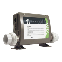
Visual guide to system wiring and DIP switch configurations.
Details power requirements and system output configurations for 16A service.
Specifies power needs and system outputs for 32A service.
Instructions on how to place the system into Test Mode using DIP Switch 1.
Guidance on how to exit Test Mode and return to normal operation.
Steps to navigate and select desired setup numbers.
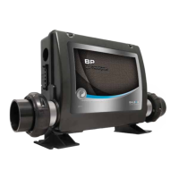
| System Type | Spa Control System |
|---|---|
| Number of Pumps Supported | 2 |
| Number of Heaters Supported | 1 |
| Voltage | 120V/240V |
| Maximum Load Current | 50A |
| Pump 1 | 2-speed |
| Pump 2 | 2-speed, 240V |
| Ozone | Optional |
| A/V | No |
| WiFi | Optional |
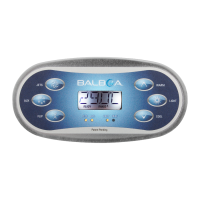
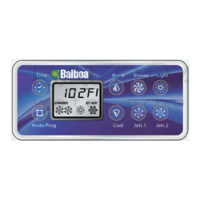
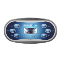
| Panel Type | Topside |
| Temperature Range | 60-104°F |