– 16 –
Materials required (included in the scope of delivery):
Baldus® Touch, 4 Allen screws (size M5) and 4 washers
for the Baldus® Touch, connecting hose between the Bal-
dus® Touch and Baldus® Bag T, Baldus® Bag T, 4 screws
(size M3) and 4 washers for the Baldus® Bag T, power sup-
ply cable
Baldus® Touch assembly:
Caution! Soiling can penetrate into the housing (e.g.
when installing in a wall), with the risk of an electric
shock or unit damage/destruction!
Connecting the pressure reducers
to the mixer
Use the blue pressure hose to connect the N
2
O pressure
reducer to the mixer. The white hose is therefore used
to connect the O
2
pressure reducer to the mixer. The
pressure hoses are mounted to the back of the mixer;
DISS connections with O-rings are used for this. As the
connectors are dierent sizes, there is no possibility of
confusion.
Assembling the Baldus® Touch mixer
and Baldus® Bag T
The Baldus® Touch oxygen-nitrous oxide mixer is in-
stalled in the Baldus® All-in-One-Cart or plasterboard
(at least 12.5 mm), see photos. The units must not be in-
stalled in carts which are not approved by Baldus®.
Fig. 13: Pressure reducers connected to gas cylinders
Fig. 14: Baldus®
All-in-One-Cart for
Baldus® Touch
designed for
installation
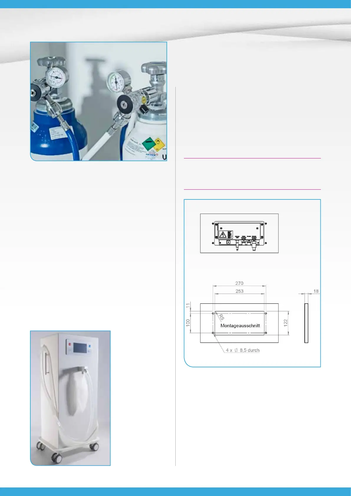
Fig. 15: Baldus® Touch dimensions in mm
1. Attach at a height at which the practitioner is ideally
looking straight on at the monitor.
2. Draw a mounting cut-out of 253 mm in width and
122 mm in height.
3. Now mark the holes for the 4 screws (size M5):
3.1. Go 8.5 mm from the top left and top right cor-
ners of the mounting cut-out to the respective
side and 11 mm downwards. In each case, draw
a point there for the centre of the rst two holes
(see illustration).